
Free CCNA v1.1 200-301 | Complete Course 2026
The official YouTube playlist for Jeremy's CCNA course.
Support:
- https://www.linkedin.com/company/jeremysitlab
- https://www.youtube.com/@JeremysITLab
- discord.com/invite/pkBYDnqFD9
- https://www.jeremysitlab.com
- https://x.com/jeremysitlab
Labs
This is the YouTube playlist of all the labs from Jeremy's IT CCNA course that I've completed.
Day 1
What is a network?
A computer network is a digital telecommunications network which allows nodes to share resources.
Nodes can consist of the following devices:
- Routers
- Switches
- Firewalls
- Servers
- Clients
Clients
Clients are devices that can access a service made available by a server.
Servers
A server is a device that provides services or resources to a client.
The same device can be a client in some situations, and a server in other situations.
Switches
Switches provide connectivity to hosts within the same LAN (Local Area Network).
Routers
Routers are used to provide connectivity between LANs.
Firewalls
- They are hardware devices that filter traffic between networks.
- They monitor and control network traffic based on configured rules.
- Can either be placed inside or outside the network.
Host based firewalls are software based applications that run on individual devices.

Two hosts sit on separate LANs and need to communicate with each other. Which device provides the connectivity between those LANs?
Day 2
Ethernet
Ethernet is a collection of network protocols/standards.
Ethernet Standards
- Ethernet standards are defined in the IEEE 802.3 standard in 1983.
- IEE stands for Institute of Electrical and Electronics Engineers.
Ethernet Standards (Copper)
| Speed | Common Name | IEEE Standard | Informal Name | Maximum Length |
|---|---|---|---|---|
| 10 Mbps | Ethernet | 802.3i | 10BASE-T | 100 m |
| 100 Mbps | Fast Ethernet | 802.3u | 100BASE-T | 100 m |
| 1 Gbps | Gigabit Ethernet | 802.3ab | 1000BASE-T | 100 m |
| 10 Gbps | 10 Gig Ethernet | 802.3an | 10GBASE-T | 100 m |
UTP Cables
UTP = Unshielded Twisted Pair
They're limited to 100 meters.
- Unshielded
- Means that the wires have no metallic shield, which makes them vulnerable to electromagnetic magnetic interferences.
The twisted wires helps protect against electromagnetic magnetic interferences.
| Standard | Pairs Used |
|---|---|
| 10BASE-T / 100BASE-T | 2 pairs (4 wires) |
| 1000BASE-T / 10GBASE-T | 4 pairs (8 wires) |
UTP Cables (10BASE-T, 100BASE-T)
| Device Type | Transmit (Tx) Pins | Receive (Rx) Pins |
|---|---|---|
| Router | 1 and 2 | 3 and 6 |
| Firewall | 1 and 2 | 3 and 6 |
| PC | 1 and 2 | 3 and 6 |
| Switch | 3 and 6 | 1 and 2 |
Fiber-Optic Connections
There are two types of fiber cables:
- Single-mode (SMF)
- Multimode (MMF)
Multimode Fiber
- Core diameter is wider than single-mode fiber.
- Allows multiple angles (modes) of light waves to enter the fiberglass core.
- Allows longer cables than UTP, but shorter cables than single-mode fiber.
- Cheaper than single-mode fiber.
Single-Mode Fiber
- Core diameter is narrower than multimode fiber.
- Light enters at a single angle (mode) from a laser-based transmitter.
- Allows longer cable lengths than both UTP and multimode fiber.
- More expensive then single-mode fiber.
Fiber-Optic Cable Standards
| Informal Name | IEEE Standard | Speed | Cable Type | Maximum Length |
|---|---|---|---|---|
| 1000BASE-LX | 802.3z | 1 Gbps | Multimode or Single-Mode | 550 m (MM) / 5 km (SM) |
| 10GBASE-SR | 802.3ae | 10 Gbps | Multimode | 400 m |
| 10GBASE-LR | 802.3ae | 10 Gbps | Single-Mode | 10 km |
| 10GBASE-ER | 802.3ae | 10 Gbps | Single-Mode | 30 km |
UTP vs Fiber-Optic Cabling
| UTP | Fiber-Optic |
|---|---|
| Lower cost than fiber-optic. | Higher cost than UTP. |
| Shorter maximum distance than fiber-optic (~100m). | Longer maximum distance than UTP. |
| Can be vulnerable to EMI (Electromagnetic Interference). | No vulnerability to EMI. |
| RJ45 ports used with UTP are cheaper than SFP ports. | SFP ports are more expensive than RJ45 ports (single-mode is more expensive than multimode). |
| Emit (leak) a faint signal outside of the cable, which can be copied (= security risk). | Does not emit any signal outside of the cable (= no security risk). |
On a 10BASE-T or 100BASE-T link, which device transmits on pins 3 and 6 and receives on pins 1 and 2?
Day 3
Protocols and Standards
A protocol is a set of rules defining how data should be communicated between devices over a network.
Who defines the standards?
Most networking standards are developed by independent standards organizations, not a single vendor, with participation from engineers at many companies.
| Organization | Role | Examples |
|---|---|---|
| IEEE (Institute of Electrical and Electronics Engineers) | Develops many of the technologies used on local area networks | Ethernet (802.3), Wi-Fi (802.11) |
| IETF (Internet Engineering Task Force) | Open community that defines protocols used on the Internet | TCP, IP, UDP, HTTP, DNS, etc. |
The TCP/IP Model
Layer 1: The Physical Layer
- Responsible for sending and receiving bits as electrical, optical, or radio signals over the medium.
- Defines things like cables, connectors, signal levels, and link speeds.
- Examples: copper UTP cables, fiber-optic cables, Wi-Fi radios and antennas, network interface cards (NICs).
Layer 2: The Local Network Layer
- Provides hop-to-hop delivery of messages on a local network.
- A hop is a one step along the path between two devices: from one router or host, to the next router or host in the path.
- Uses MAC (Media Access Control) addresses to identify interfaces.
- Each device connected to a LAN has a unique MAC address assigned to it.
- Protocols at this layer include:
- Ethernet (IEEE 802.3)
- Wi-Fi (IEEE 802.11)
Layer 3: The Internet Layer
- Provides end-to-end delivery between hosts across multiple networks.
- Uses IP addresses to identify hosts on a network.
- Routers operate at this layer, using the message's destination IP address to forward the message toward its final destination host.
- Protocols at this layer include:
- IP (IPv4, IPv6)
- ICMP (Internet Control Message Protocol)
Layer 4: The Transport Layer
- Provides end-to-end communication between application processes.
- Uses port numbers to identify the processes on each host.
- Runs mainly on the communicating hosts.
- Protocols at this layer include:
- UDP (User Datagram Protocol)
- TCP (Transmission Control Protocol)
Layer 5: The Application Layer
- The Application layer (layer 5) is where network communications meet applications.
- Defines how application processes format, send, and interpret data.
- Protocols at this layer define message formats and rules for specific tasks, such as:
- Browsing web pages (HTTP/HTTPS)
- Transferring files (FTP/TFTP)
- Sending/Receiving email (SMTP, POP3, IMAP)
- Network infrastructure devices (routers, switches) don't care about application-layer details.
Encapsulation & Decapsulation
Protocol Data Units
- The combination of data and a L4 header is called a segment (TCP) or datagram (UDP).
- The combination of a segment/datagram and a L3 header is called a packet.
- The combination of a packet and a L2 header/trailer is called a frame. - The frame is what gets sent over the physical medium.
The OSI Model
Other Versions
What do you call a packet once a Layer 2 header and trailer have been added to it?
Day 4
User EXEC Mode
Router>
- The
>symbol indicates that you're in user EXEC mode. Routeris the hostname of the device.- User EXEC mode is very limited.
- Not able to make changes to the configuration.
Privileged EXEC Mode
To enter privileged EXEC mode from user EXEC mode you must run the enable command.
Router>enable
Router#
- The
#symbol indicates that you're in privileged EXEC mode. - Provides complete access to view the device's configuration, restart the device, etc.
- Cannot change the configuration, but can change the time on the device, save the configuration file, etc.
Global Configuration Mode
To make changes to any of the configurations on the device you must enter global configuration mode.
Router>enable
Router#configure terminal
Enter configuration commands, one per line. End with CNTL/Z.
Router(config)#
The configure terminal command enters global configuration mode.
Enable Password
You don't want just anyone to have the ability to make changes to the network configuration for security purposes, so must protect privileged EXEC mode with a password.
Router(config)#enable password CCNA
CCNA is the password.
- Passwords are case-sensitive.
Running-Config / Startup-Config
- There are two separate configuration files kept on the device at once.
running-configis the current, active configuration file on the device. As you enter commands in the CLI, you edit the active configuration.
To look at the configuration file:
Router#show running-config
Building configuration...

Current configuration : 714 bytes
!
version 15.1
no service timestamps log datetime msec
no service timestamps debug datetime msec
no service password-encryption
!
hostname Router
!
!
!
enable password CCNA
!
To run the startup-config file:
Router#show startup-config
startup-config is not present
startup-config is not present this is because we haven't have saved the running config.
Saving The Configuration
Router#write
Building configuration...
 [OK]
Router# copy running-config startup-config
Destination filename [startup-config]?
Building configuration...
 [OK]
Router#
Service Password-Encryption
Router#configure terminal
Enter configuration commands, one per line. Ed with CNTL/Z.
Router(config)#service password-encryption
service password-encryption will encrypt all passwords.
service password-encryption is not very secure.
Enable Secret
The more secure version to encrypt passwords is the enable secret command.
Router(config)#enable secret Cisco
Cisco is the password.
enable secret uses the MD5 hashing algorithm.
If both the enable secret and enable password are configured, then the whatever password you had setup for enable password will be ignored.
enable secret is always encrypted by default.
Cancelling Commands
Router(config)#no service password-encryption
- The
nokeyword disable encryption for future passwords. - Passwords that were already encrypted will not be decrypted.
Service Password-Encryption Summary
If you enable service password-encryption:
- Current passwords will be encrypted.
- Future passwords will be encrypted.
- The
enable secretwill not be affected (it's always encrypted).
If you disable service password encryption:
- Current passwords will not be decrypted.
- Future passwords will not be encrypted.
enable secretwill not be affected.
A router has both an enable password and an enable secret configured. Which one do you need to enter to reach privileged EXEC mode?
Day 5 (Part 1)
Local Area Networks (LANs)
Local area networks are networks confined to a small area like a home or small office.
- Routers are use to connect separate LANs.
OSI Model - PDUs
The different stages of preparing data to be forwarded are Protocol Data Units (PDUs).
Ethernet Frame
There are 5 fields in the ethernet frame header:
- Preamble
- SFD (Start Frame Delimiter)
- Destination
- Source
- Type (or Length)
There is only 1 field in the ethernet frame trailer:
- FCS (Frame Check Sequence)
- Used by the receiving device to check if any errors occurred during the transmission.
Key points:
- The header and trailer are 26 bytes in length.
- The minimum size for an Ethernet frame is 64 bytes.
- The minimum payload for the Ethernet frame is 46 bytes.
- If the payload is less than 46 bytes, padding bytes are added.
Preamble & SFD
Preamble:
- Length: 7 bytes (56 bits).
- Alternating 1's and 0's.
- Allows devices to synchronize their receiver clocks.
SFD:
- Stands for 'Start Frame Delimiter'.
- Length: 1 byte (8 bits).
- Marks the end of the preamble, and the beginning of the rest of the frame.
The Preamble & SFD is usually not considered part of the Ethernet header. Therefore the size of the Ethernet header + trailer is 18 bytes.
Destination & Source
- Indicate the devices sending and receiving the frame.
- Mainly consist of the destination and source MAC address.
- MAC = Media Access Control.
- 6 byte (48 bit) address of the physical device.
Type / Length
- 2 bytes (16 bits).
- A value of 1500 or less in this field indicates the length of the encapsulated packet.
- A value of 1536 or greater in this field indicates the type of encapsulated packet, and the length is determined via other methods.
Frame Check Sequence (FCS)
- Stands for 'Frame Check Sequence'.
- 4 bytes (32 bits).
- Detects corrupted data by running a 'CRC' algorithm over the received data.
- CRC = 'Cyclic Redundancy Check'.
MAC Address
- Is globally unique.
- The first 3 bytes are the OUI (Organizationally Unique Identifier), which is assigned to the company making the device.
- The last 3 bytes are unique to the device itself.
- Written as 12 hexadecimal characters.
A switch receives an Ethernet frame whose Type/Length field holds the value 1500. What does that value tell the receiving device?
Day 6 (Part 2)
ARP
- ARP stands for 'Address Resolution Protocol'.
- APR is used to discover the Layer 2 address (MAC address) of a known Layer 3 address (IP address).
- Consists of two messages:
- ARP Request
- ARP Reply
- ARP Request is broadcast (sent to all hosts on the network).
- ARP Reply is unicast (the host that sent the request).
Ping
- A network utility that is used to test reachability.
- Measures round-trip time.
- Uses two messages:
- ICMP Echo Request
- ICMP Echo Reply
MAC Address Table
The command to view the MAC address table on a Cisco switch:
SW1#show mac address-table
          Mac Address Table
-------------------------------------------

Vlan    Mac Address       Type        Ports
----    -----------       --------    -----
   1    0c2f.b011.9d00    DYNAMIC     Gi0/0
   1    0c2f.b06a.3900    DYNAMIC     Gi0/2
Total Mac Addresses for this criterion: 2
SW1#
Clearing the MAC Address Table
This command will remove all dynamic MAC addresses from the table:
Total Mac Addresses for this criterion: 2
SW1#clear mac address-table dynamic
SW1#show mac address-table
          Mac Address Table
-------------------------------------------

Vlan    Mac Address       Type        Ports
----    -----------       --------    -----
SW1#
clear mac address-table dynamic
If the switch doesn't get any traffic from a certain MAC address for 5 minutes, it will remove the entry from the MAC address table, this process is called aging.
To remove a certain MAC address from the table:
SW1#clear mac address-table dynamic address 0c2f.b011.9d00
SW1#show mac address-table
          Mac Address Table
-------------------------------------------

Vlan    Mac Address       Type        Ports
----    -----------       --------    -----
   1    0c2f.b06a.3900    DYNAMIC     Gi0/2
Total Mac Addresses for this criterion: 1
SW1#
clear mac address-table dynamic address mac-address
You can clear a MAC address from the table by specifying the interface/port:
SW1#clear mac address-table dynamic interface Gi0/0
SW1#show mac address-table
          Mac Address Table
-------------------------------------------

Vlan    Mac Address       Type        Ports
----    -----------       --------    -----
   1    0c2f.b06a.3900    DYNAMIC     Gi0/2
Total Mac Addresses for this criterion: 1
SW1#
clear mac address-table dynamic interface interface-id
A host knows the IP address of another host on its LAN, but not its MAC address. How are the two ARP messages that follow addressed?
Day 7 (Part 1)
IPv4 Header
- IP addresses are 32 bits (4 bytes) in length.
IPv4 Addresses
An example IPv4 address:
192.168.1.254/24
- Each group is 8 bits.
- Each 8 bit group is called an octet.
- The
/24means the first 24 bits represents the network portion of the address. - The remaining 8 bits represents the end host portion.
So 192.168.1 is the network portion and .254 is the host portion.
IPv4 Address Classes
| Class | First octet | First octet numeric range |
|---|---|---|
| A | 0xxxxxxx | 0-127 |
| B | 10xxxxxx | 128-191 |
| C | 110xxxxx | 192-223 |
| D | 1110xxxx | 224-239 |
| E | 1111xxxx | 240-255 |
Classes A, B and C are the classes used for hosts, and each has a default prefix length:
| Class | First octet | First octet numeric range | Prefix Length |
|---|---|---|---|
| A | 0xxxxxxx | 0-127 | /8 |
| B | 10xxxxxx | 128-191 | /16 |
| C | 110xxxxx | 192-223 | /24 |
The prefix length determines how many networks each class has, and how many addresses are in each of those networks:
| Class | Leading bits | Size of network number bit field | Size of rest bit field | Number of networks | Addresses per network |
|---|---|---|---|---|---|
| Class A | 0 | 8 | 24 | 128 (27) | 16,777,216 (224) |
| Class B | 10 | 16 | 16 | 16,384 (214) | 65,536 (216) |
| Class C | 110 | 24 | 8 | 2,097,152 (221) | 256 (28) |
Loopback Addresses
- Addresses range
127.0.0.0-127.255.255.255. - Used to test the network stack on the local device.
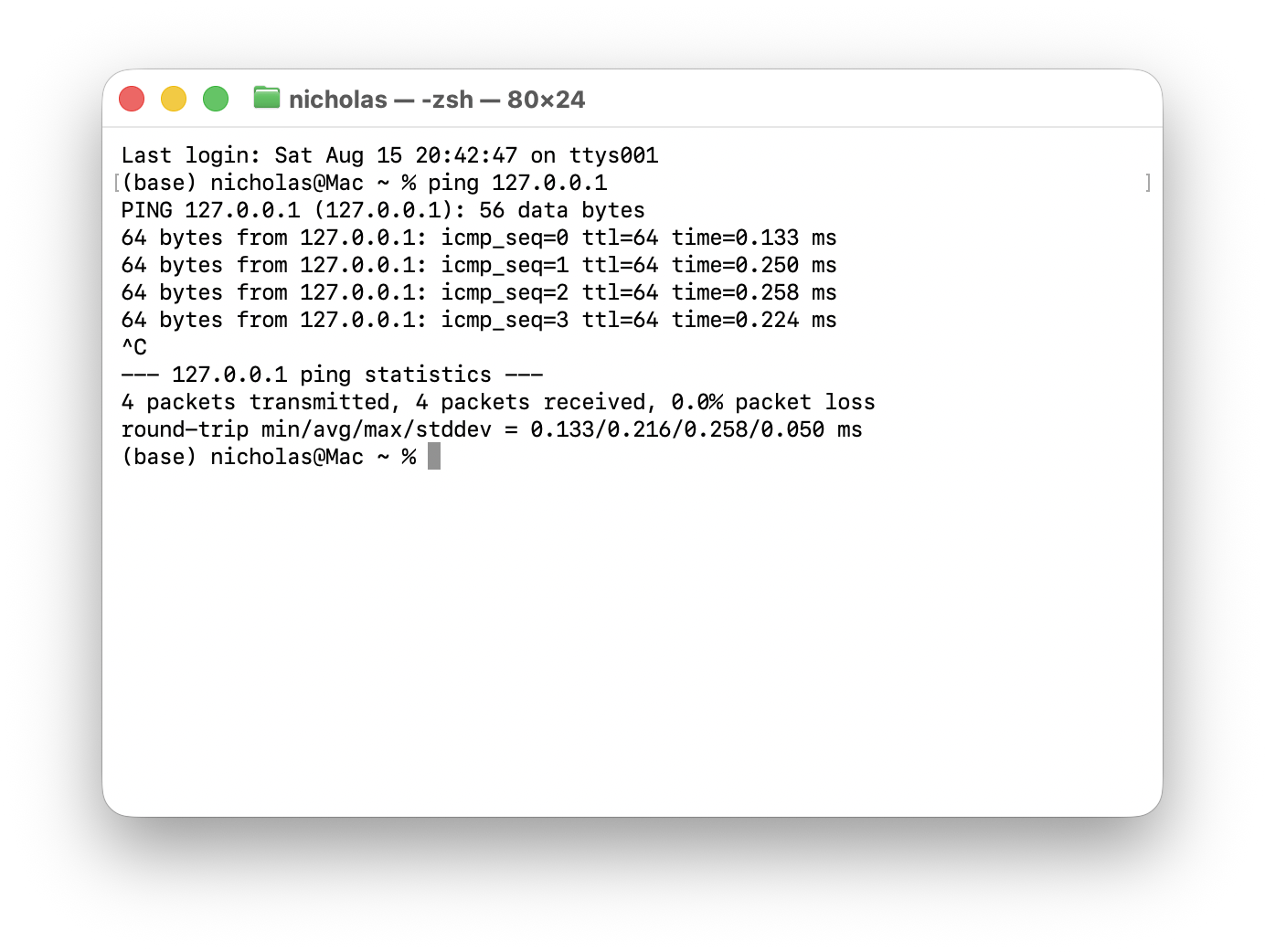
Netmask
A netmask (also called a subnet mask) is another way of writing the prefix length. It's a 32 bit value where the bits belonging to the network portion are set to 1, and the bits belonging to the host portion are set to 0.
So /24 and 255.255.255.0 mean exactly the same thing: the first 24 bits are the network portion.
| Class | Prefix Length | Netmask | Netmask in binary |
|---|---|---|---|
| A | /8 | 255.0.0.0 | 11111111 00000000 00000000 00000000 |
| B | /16 | 255.255.0.0 | 11111111 11111111 00000000 00000000 |
| C | /24 | 255.255.255.0 | 11111111 11111111 11111111 00000000 |
Network Address
- Host portion of the address is all 0's = Network Address.
- The network address cannot be assigned a host.
Broadcast Address
- Host portion of the address is all 1's = Broadcast Address.
- The broadcast address cannot be assigned to a host.
A host is configured with the address 172.16.5.10/16. Which address is the broadcast address of the network it belongs to?
Day 8 (Part 2)
Viewing Interfaces
The command to view a summary of all the interfaces on a router:
R1>en
R1#show ip interface brief
Interface              IP-Address      OK? Method Status                Protocol
GigabitEthernet0/0     unassigned      YES unset  administratively down down
GigabitEthernet0/1     unassigned      YES unset  administratively down down
GigabitEthernet0/2     unassigned      YES unset  administratively down down
GigabitEthernet0/3     unassigned      YES unset  administratively down down
R1#
show ip interface brief
- Lists every interface on the device, its IP address, and whether it's up or down.
unassignedmeans no IP address has been configured on the interface yet.- Status is the Layer 1 state, and Protocol is the Layer 2 state.
administratively downmeans the interface has been manually disabled, router interfaces are disabled by default.- This is the default status of Cisco router interfaces.
- Cisco switch interfaces are not
administratively downby default.
Switch interfaces do not have the 'shutdown' command applied by default. They will have the up/up state if connected to another device, or the down/down state if they're not.
Configuring an Interface
To configure an interface you first have to enter interface configuration mode:
R1#conf t
Enter configuration commands, one per line.  End with CNTL/Z.
R1(config)#interface gigabitethernet 0/0
R1(config-if)#
interface interface-id
conf tis short forconfigure terminal, which takes you from privileged EXEC mode into global configuration mode.interface gigabitethernet 0/0selects the interface you want to configure.- The prompt changes from
R1(config)#toR1(config-if)#, which tells you any commands you type now will apply to that interface only.
Assigning an IP Address to an Interface
Once you're in interface configuration mode you can give the interface an IP address and enable it:
R1(config-if)#ip address 10.255.255.254 ?
  A.B.C.D  IP subnet mask

R1(config-if)#ip address 10.255.255.254 255.0.0.0
R1(config-if)#no shutdown
R1(config-if)#
*Dec  7 08:29:08.937: %LINK-3-UPDOWN: Interface GigabitEthernet0/0, changed state to up
*Dec  7 08:29:09.938: %LINEPROTO-5-UPDOWN: Line protocol on Interface GigabitEthernet0/0, changed state to up
R1(config-if)#
ip address ip-address netmask
- The
?shows you what the router expects next, in this case the netmask. - The netmask has to be written out in full (
255.0.0.0), you can't use the/8prefix notation here. no shutdownenables the interface, this is what takes it out of theadministratively downstate.- The two messages that follow are the router telling you the interface came up:
- %LINK-3-UPDOWN is Layer 1 (the Status column) coming up.
- %LINEPROTO-5-UPDOWN is Layer 2 (the Protocol column) coming up.
Running Show Commands from Configuration Mode
show commands normally only work in privileged EXEC mode, but you can run them from configuration mode by putting do in front:
R1(config-if)#do show ip interface brief
Interface              IP-Address      OK? Method Status                Protocol
GigabitEthernet0/0     10.255.255.254  YES manual up                    up
GigabitEthernet0/1     unassigned      YES unset  administratively down down
GigabitEthernet0/2     unassigned      YES unset  administratively down down
GigabitEthernet0/3     unassigned      YES unset  administratively down down
R1(config-if)#
do show-command
- Saves you from having to
exitback to privileged EXEC mode just to check something. - Gi0/0 is now the only interface with an IP address, and its Status and Protocol are both
up. - The Method changed from
unsettomanual, which means the address was configured by hand.
Show Interfaces [Interface]
show ip interface brief gives you a summary of every interface, show interfaces gives you everything about one interface:
R1#show interfaces g0/0
GigabitEthernet0/0 is up, line protocol is up
  Hardware is iGbE, address is 0c1b.8444.f000 (bia 0c1b.8444.f000)
  Internet address is 10.255.255.254/8
  MTU 1500 bytes, BW 1000000 Kbit/sec, DLY 10 usec,
     reliability 255/255, txload 1/255, rxload 1/255
  Encapsulation ARPA, loopback not set
  Keepalive set (10 sec)
  Auto Duplex, Auto Speed, link type is auto, media type is RJ45
  output flow-control is unsupported, input flow-control is unsupported
  ARP type: ARPA, ARP Timeout 04:00:00
  Last input 00:00:06, output 00:00:05, output hang never
  Last clearing of "show interface" counters never
  Input queue: 0/75/0/0 (size/max/drops/flushes); Total output drops: 0
  Queueing strategy: fifo
  Output queue: 0/40 (size/max)
  5 minute input rate 0 bits/sec, 0 packets/sec
  5 minute output rate 0 bits/sec, 0 packets/sec
     167 packets input, 30159 bytes, 0 no buffer
     Received 0 broadcasts (0 IP multicasts)
     0 runts, 0 giants, 0 throttles
     0 input errors, 0 CRC, 0 frame, 0 overrun, 0 ignored
     0 watchdog, 0 multicast, 0 pause input
     350 packets output, 39097 bytes, 0 underruns
     0 output errors, 0 collisions, 2 interface resets
     105 unknown protocol drops
     0 babbles, 0 late collision, 0 deferred
     1 lost carrier, 0 no carrier, 0 pause output
     0 output buffer failures, 0 output buffers swapped out
show interfaces interface-id
g0/0is shorthand forGigabitEthernet0/0.- If you leave the interface off the end, it shows this same output for every interface on the device.
is up, line protocol is upis the same Layer 1 / Layer 2 state as the Status and Protocol columns.address is 0c1b.8444.f000is the MAC address of the interface, andbia(burned in address) is the one that came from the factory.Internet address is 10.255.255.254/8is the IP address and prefix length configured on the interface.MTU 1500 bytesis the largest packet the interface will send without breaking it up.BW 1000000 Kbit/secis the bandwidth (1 Gbps).- The counters at the bottom (
input errors,CRC,collisions, etc) are what you use to troubleshoot a link, they should all be 0 on a healthy interface.
Show Interfaces Description
R1#show interfaces description
Interface                      Status         Protocol Description
Gi0/0                          up             up
Gi0/1                          up             up
Gi0/2                          up             up
Gi0/3                          admin down     down
show interfaces description
- Gives you a shorter summary than
show ip interface brief, no IP addresses, just the state of each interface. - The Description column is empty because no descriptions have been configured yet.
- A description is just a label you give an interface to remind you what it connects to, it has no effect on how the interface works.
admin downis the short way of writingadministratively down.
Adding a Description to an Interface
You add a description from interface configuration mode:
R1(config)#int g0/0
R1(config-if)#description ## to SW1 ##
R1(config-if)#int g0/1
R1(config-if)#desc ## to SW2 ##
R1(config-if)#int g0/2
R1(config-if)#desc ## to SW3 ##
R1(config-if)#do sh int desc
Interface                      Status         Protocol Description
Gi0/0                          up             up       ## to SW1 ##
Gi0/1                          up             up       ## to SW2 ##
Gi0/2                          up             up       ## to SW3 ##
Gi0/3                          admin down     down
description text
descis short fordescription, andintis short forinterface.- You don't have to
exitbetween interfaces, typingint g0/1while in(config-if)mode just moves you straight to the next interface. - The
##are not special, they're just there to make the description stand out in the output. - Gi0/3 has no description because one was never set on it.
You configure an IP address on a router interface, but `show ip interface brief` still shows it as administratively down. What do you need to do to bring it up?
Day 9
Show Interfaces Status
SW1#show interfaces status
Port      Name               Status       Vlan       Duplex  Speed Type
Fa0/1                        connected    1          a-full  a-100 10/100BaseTX
Fa0/2                        connected    trunk      a-full  a-100 10/100BaseTX
Fa0/3                        connected    1          a-full  a-100 10/100BaseTX
Fa0/4                        connected    1          a-full  a-100 10/100BaseTX
Fa0/5                        notconnect   1            auto   auto 10/100BaseTX
Fa0/6                        notconnect   1            auto   auto 10/100BaseTX
Fa0/7                        notconnect   1            auto   auto 10/100BaseTX
Fa0/8                        notconnect   1            auto   auto 10/100BaseTX
Fa0/9                        notconnect   1            auto   auto 10/100BaseTX
Fa0/10                       notconnect   1            auto   auto 10/100BaseTX
Fa0/11                       notconnect   1            auto   auto 10/100BaseTX
Fa0/12                       notconnect   1            auto   auto 10/100BaseTX
show interfaces status
- Port is the interface,
Fa0/1is short forFastEthernet0/1. - Name is the description set on the port.
- Status is whether the port is up:
connected= something is plugged in.notconnect= nothing is plugged in.disabled= the port was shut down.
- Vlan is the VLAN the port is in,
1is the default.trunkmeans the port carries multiple VLANs.
- Duplex is
full(send and receive at once) orhalf(one at a time). - Speed is the speed of the port in Mbps.
- Type is the physical port,
10/100BaseTXis copper RJ45 that runs at 10 or 100 Mbps.
a- means autonegotiated, the two devices agreed on the speed and duplex themselves.
- Ports with nothing plugged in just say
autobecause there's nothing to negotiate with.
Configuring Interface Speed and Duplex
SW1#conf t
Enter configuration commands, one per line.  End with CNTL/Z.
SW1(config)#int f0/1
SW1(config-if)#speed ?
  10    Force 10 Mbps operation
  100   Force 100 Mbps operation
  auto  Enable AUTO speed configuration
SW1(config-if)#speed 100
SW1(config-if)#duplex ?
  auto  Enable AUTO duplex configuration
  full  Force full duplex operation
  half  Force half-duplex operation
SW1(config-if)#duplex full
SW1(config-if)#description ## to R1 ##
speed 10 | 100 | auto
duplex auto | full | half
speedandduplexare set in interface configuration mode.?shows you the options you can use with a command.- The options are the speeds the port supports.
- Setting a speed or duplex forces it, the port stops autonegotiating and uses what you told it.
autoputs it back to autonegotiating.descriptionsets the description for that interface.
Interface Range
SW1(config)#interface range f0/5 - 12
SW1(config-if-range)#description ## not in use ##
SW1(config-if-range)#shutdown
00:42:36: %LINK-5-CHANGED: Interface FastEthernet0/5, changed state to administratively down
00:42:36: %LINK-5-CHANGED: Interface FastEthernet0/6, changed state to administratively down
00:42:36: %LINK-5-CHANGED: Interface FastEthernet0/7, changed state to administratively down
00:42:36: %LINK-5-CHANGED: Interface FastEthernet0/8, changed state to administratively down
00:42:36: %LINK-5-CHANGED: Interface FastEthernet0/9, changed state to administratively down
00:42:36: %LINK-5-CHANGED: Interface FastEthernet0/10, changed state to administratively down
00:42:36: %LINK-5-CHANGED: Interface FastEthernet0/11, changed state to administratively down
00:42:36: %LINK-5-CHANGED: Interface FastEthernet0/12, changed state to administratively down
SW1(config-if-range)#
interface range interface-id - interface-id
interface rangelets you configure lots of interfaces at once instead of one at a time.f0/5 - 12means f0/5 up to f0/12, that's 8 interfaces.- The prompt changes to
(config-if-range)to show you're editing a group of interfaces. - Every command you enter is applied to all of them, so all 8 got the same description and were shut down.
- Shutting down unused ports is good practice, it stops anyone plugging into a spare port to get onto the network.
SW1(config)#int range f0/5 - 6, f0/9 - 12
SW1(config-if-range)#no shut
00:57:07: %LINK-3-UPDOWN: Interface FastEthernet0/5, changed state to up
00:57:07: %LINK-3-UPDOWN: Interface FastEthernet0/6, changed state to up
00:57:07: %LINK-3-UPDOWN: Interface FastEthernet0/9, changed state to up
00:57:07: %LINK-3-UPDOWN: Interface FastEthernet0/10, changed state to up
00:57:07: %LINK-3-UPDOWN: Interface FastEthernet0/11, changed state to up
00:57:07: %LINK-3-UPDOWN: Interface FastEthernet0/12, changed state to up
interface range interface-id - interface-id, interface-id - interface-id
- You can select more than one range at a time by separating them with a comma.
f0/5 - 6, f0/9 - 12selects f0/5, f0/6, and f0/9 to f0/12, f0/7 and f0/8 are skipped.no shutis short forno shutdown, it turns the interfaces back on.
Full/Half Duplex
- Half duplex means that the device cannot send and receive data at the same time. If it is receiving a frame, it must wait before sending a frame.
- Full duplex means that the device can send and receive data at the same time.
Devices connected to hubs must operate in half duplex.
CSMA/CD
- Stands for 'Carrier Sense Multiple Access with Collision Detection'.
- Before sending frames, devices listen to the collision domain until they detect that other devices are not sending traffic.
- If a collision does occur, the device sends a jamming signal to inform the other devices that a collision has occurred.
- Each device will wait a random period of time before sending frames again.
- This whole process repeats.
Speed/Duplex Autonegotiation
- Interfaces that can run at different speeds (10/100 or 10/100/1000) have default setting of speed auto and duplex auto.
- Interfaces tell the device on the other end what they're capable of, and the two agree on the fastest speed and best duplex they can both do.
If autonegotiation is disabled on the other device, the switch has to work it out on its own:
- Speed: the switch tries to sense what speed the other device is running at.
- If it can't, it uses the slowest speed it supports (10 Mbps on a 10/100/1000 interface).
- Duplex: the switch picks the duplex based on the speed it ended up with.
- 10 or 100 Mbps = half duplex.
- 1000 Mbps or faster = full duplex.
Duplex Mismatch
A duplex mismatch is when one end of a link is on full duplex and the other end is on half duplex.
It happens because the switch can sense the speed the other device is using, but it can't sense the duplex, so it has to guess with the rule above.
Here's a switch on auto with 3 PCs that were all set manually:
| PC is set to | Switch senses | Switch guesses | Result |
|---|---|---|---|
| 10 Mbps / half | 10 Mbps | half duplex | match |
| 1000 Mbps / full | 1000 Mbps | full duplex | match |
| 100 Mbps / full | 100 Mbps | half duplex | mismatch |
The last one breaks because the switch always guesses half duplex at 100 Mbps, but the PC was set to full.
What goes wrong:
- The full duplex end sends whenever it wants, it doesn't check if the line is busy.
- The half duplex end is using CSMA/CD, so frames arriving while it's sending look like a collision.
- It stops, waits, then sends the frame again.
The link still works, it's just slow, and it gets worse the more traffic you put through it.
- The half duplex end shows late collisions.
- The full duplex end shows CRC errors and runts.
- Both show up in the counters at the bottom of
show interfaces.
The fix is to make both ends match, either put both on auto or set both manually to the same thing.
Interface Errors
These are the counters at the bottom of show interfaces:
269 packets input, 71059 bytes, 0 no buffer
Received 6 broadcasts, 0 runts, 0 giants, 0 throttles
0 input errors, 0 CRC, 0 frame, 0 overrun, 0 ignored
7290 packets output, 429075 bytes, 0 underruns
0 output errors, 3 interface resets
0 output buffer failures, 0 output buffers swapped out
- Runts are frames smaller than the minimum frame size (64 bytes).
- Giants are frames larger than the maximum frame size (1518 bytes).
- CRC are frames that failed the CRC (Cyclic redundancy check) check in the Ethernet FCS trailer.
- Frame are frames with an incorrect format, caused by an error.
- Input errors is the total of the above four and a few others.
- Output errors are frames the switch tried to send but couldn't because of an error.
A PC is set manually to 100 Mbps and full duplex, and the switch port it connects to is left on auto. What happens on that link?
Day 10
IPv4 Header - Version Field
- Length: 4 bits.
- Identifies the version of IP being used.
- There are two versions:
- IPv4 = 4 (0100)
- IPv6 = 6 (0110)
IPv4 Header - Internet Header Length (IHL)
- The final field of the IPv4 header (Options) is dynamic (it can have a variable length), so this field is necessary to indicate the total length of the header.
- Identifies the length of the header in 4-byte increments.
- Value
5=5 * 4-bytes = 20 bytes.
- Value
- Minimum value is 5 (20 bytes).
- Maximum value is 15 (
15 * 4 = 60, 60 bytes).
IPv4 Header - DSCP Field
- Stands for 'Differential Services Code Point'.
- Length: 6 bits.
- Used for QoS (Quality of Service).
- Used to prioritize delay-sensitive data.
IPv4 Header - ECN Field
- Stands for 'Explicit Congestion Notification'.
- Length: 2 bits.
- Provides end-to-end (between two endpoints) notification of network congestion without dropping packets.
- Optional feature that requires both endpoints, as well as the underlying network infrastructure, to support it.
Further Reading: https://www.geeksforgeeks.org/computer-networks/what-is-ecnexplicit-congestion-notification/
IPv4 Header - Total Length Field
- Length: 16 bits.
- Indicates the total length of the packet.
- Measured in bytes (not 4-byte increments like Internet Header Length (IHL)).
- Minimum value of 20 (with no encapsulated data).
- Maximum value of 65,535 (maximum 16-bit value).
IPv4 Header - Identification Field
- Length: 16 bits.
- If a packet is fragmented due to being too large, this field is used to identify which packet the fragment belongs to.
- All fragments of the same packet will have their own IPv4 header with the same value in this field.
- Packets are fragmented if larger than the MTU (Maximum Transmission Unit).
- The MTU is usually 1500 bytes.
- Fragments are reassembled by the receiving host.
IPv4 Header - Flags Field
- Length: 3 bits.
- Used to control/identify fragments.
- Bit 0: Reserved, always set to 0.
- Bit 1: Don't Fragment (DF bit), used to indicate a packet that should not be fragmented.
- Bit 2: More Fragments (MF bit), set to 1 if there are more fragments in the packet, set to 0 for the last fragment.
IPv4 Header - Fragment Offset Field
- Length: 13 bits.
- Used to indicate the position of the fragment within the original unfragmented IP packet.
- Allows fragmented packets to be reassembled even if the fragments arrive out of order.
IPv4 Header - Time To Live Field
- Length: 8 bits.
- A router will drop a packet with a TTL of 0.
- It prevents a packet from circulating around the network forever.
- Indicates a 'hop count': each time the packet arrives at a router, the router decreases the TTL by 1.
- Recommended default TTL is 64.
IPv4 Header - Protocol Field
- Length: 8 bits.
- Indicates the protocol used at layer 4.
- Example protocols:
- 6: TCP
- 17: UDP
- 1: ICMP
- 89: OSPF (dynamic routing protocol)
https://en.wikipedia.org/wiki/List_of_IP_protocol_numbers
IPv4 Header - Header Checksum Field
Used to check whether the IPv4 header has been corrupted or changed while traveling across the network
- Length: 16 bits.
- A calculated checksum used to check for errors in the IPv4 header.
- When a router receives a packet, it calculates the checksum of the header and compares it to the one in this field of the header.
- If they do not match, the router drops the packet.
- Not used to check for errors in the encapsulated data.
- IP relies on the encapsulated protocol to detect errors in the encapsulated data.
- Both TCP and UDP have their own checksum fields to detect errors in the encapsulated data.
IPv4 Header - Source/Destination IP Address Fields
- Length: 32 bits.
- Source IP Address = IPv4 address of the sender of the packet.
- Destination IP Address = IPv4 address of the intended receiver of the packet.
IPv4 Header - Options
- Length: 0 - 320 bits.
- Rarely used.
- If the IHL field is greater than 5, it means that Options are present.
| Field | Size (bits) | Description |
|---|---|---|
| Copied | 1 | Set to 1 if the options need to be copied into all fragments of a fragmented packet. |
| Option Class | 2 | A general options category. 0 is for "control" options, and 2 is for "debugging and measurement". 1 and 3 are reserved. |
| Option Number | 5 | Specifies an option. |
| Option Length | 8 | Indicates the size of the entire option (including this field). This field may not exist for simple options. |
| Option Data | Variable | Option-specific data. This field may not exist for simple options. |
Wireshark Packet Capture
A router receives an IPv4 packet whose IHL field holds the value 6. How long is the header, and what does that value tell you about the Options field?
Day 11 (Part 1)
What is Routing?
Routing is the process that routers use to determine the path that IP packets should take over a network to reach their destination. Routers typically store routes to all of their known destinations in a routing table. When a router receives a packet, it looks at the routing table to find the best route to forward the packet.
There are two main routing methods:
- Dynamic Routing: Routers use dynamic routing protocols (i.e OSPF) to share routing information with each other automatically and build their routing tables.
- Static Routing: A network engineer/admin manually configures routes on the router.
A route tells the router: to send a packet to destination X, you should send the packet to next-hop (the next router in the path to the destination) Y. -> or, if the destination is directly connected to the router, send the packet directly to the destination. -> or, if the destination is the router's own IP address, receive the packet for yourself.
If a router receives a packet and it doesn't have a route that matches the packet's destination, it will drop the packet.
Routing Table (show ip route)
Use the command show ip route to view the routing table.
R1#show ip route
Codes: L - local, C - connected, S - static, R - RIP, M - mobile, B - BGP
       D - EIGRP, EX - EIGRP external, O - OSPF, IA - OSPF inter area
       N1 - OSPF NSSA external type 1, N2 - OSPF NSSA external type 2
       E1 - OSPF external type 1, E2 - OSPF external type 2
       i - IS-IS, su - IS-IS summary, L1 - IS-IS level-1, L2 - IS-IS level-2
       ia - IS-IS inter area, * - candidate default, U - per-user static route
       o - ODR, P - periodic downloaded static route, H - NHRP, l - LISP
       a - application route
       + - replicated route, % - next hop override, p - overrides from PfR

Gateway of last resort is not set

      192.168.1.0/24 is variably subnetted, 2 subnets, 2 masks
C        192.168.1.0/24 is directly connected, GigabitEthernet0/2
L        192.168.1.1/32 is directly connected, GigabitEthernet0/2
      192.168.12.0/24 is variably subnetted, 2 subnets, 2 masks
C        192.168.12.0/24 is directly connected, GigabitEthernet0/1
L        192.168.12.1/32 is directly connected, GigabitEthernet0/1
      192.168.13.0/24 is variably subnetted, 2 subnets, 2 masks
C        192.168.13.0/24 is directly connected, GigabitEthernet0/0
L        192.168.13.1/32 is directly connected, GigabitEthernet0/0
The Codes legend at the top lists the different protocols routers can use to learn routes. The two in this output are:
- L - local is a route to the actual IP address configured on the interface (with a /32 netmask).
- C - connected is a route to the network the interface is connected to (with the actual netmask configured on the interface).
When you configure an IP address on an interface and enable it with no shutdown, 2 routes per interface are automatically added to the routing table:
- A connected route.
- A local route.
Connected and Local Routes
      192.168.1.0/24 is variably subnetted, 2 subnets, 2 masks
C        192.168.1.0/24 is directly connected, GigabitEthernet0/2
L        192.168.1.1/32 is directly connected, GigabitEthernet0/2
      192.168.12.0/24 is variably subnetted, 2 subnets, 2 masks
C        192.168.12.0/24 is directly connected, GigabitEthernet0/1
L        192.168.12.1/32 is directly connected, GigabitEthernet0/1
      192.168.13.0/24 is variably subnetted, 2 subnets, 2 masks
C        192.168.13.0/24 is directly connected, GigabitEthernet0/0
L        192.168.13.1/32 is directly connected, GigabitEthernet0/0
A connected route is a route to the network the interface is connected to.
- R1's G0/2 IP address is
192.168.1.1/24. - The network address is
192.168.1.0/24. - It provides a route to all hosts in that network (i.e.
192.168.1.10,192.168.1.100,192.168.1.232, etc). - R1 knows: "If I need to send a packet to any host in the
192.168.1.0/24network, I should send it out of G0/2".
A local route is a route to the exact IP address configured on the interface.
- A /32 netmask is used to specify the exact IP address of the interface.
- /32 means all 32 bits are 'fixed', they can't change.
- Even though R1's G0/2 is configured as
192.168.1.1/24, the local route is to192.168.1.1/32. - R1 knows: "If I receive a packet destined for this IP address, the message is for me".
A route matches a packet's destination if the packet's destination IP address is part of the network specified in the route.
Route Selection
      192.168.1.0/24 is variably subnetted, 2 subnets, 2 masks
C        192.168.1.0/24 is directly connected, GigabitEthernet0/2
L        192.168.1.1/32 is directly connected, GigabitEthernet0/2
A packet destined for 192.168.1.1 is matched by both of those routes, so which one does R1 use? It chooses the most specific matching route.
- The route to
192.168.1.0/24includes 256 different IP addresses (192.168.1.0to192.168.1.255). - The route to
192.168.1.1/32includes only 1 IP address (192.168.1.1), so it is the more specific of the two.
The most specific matching route is the matching route with the longest prefix length.
So R1 selects the route to 192.168.1.1/32, which is the local route:
- R1 receives the packet for itself, rather than forwarding it out of G0/2.
- A local route means keep the packet, don't forward it.
R1's G0/2 interface is configured with 192.168.1.1/24, so its routing table holds both a connected route to 192.168.1.0/24 and a local route to 192.168.1.1/32. A packet arrives destined for 192.168.1.1, which both routes match. What does R1 do?
Day 11 (Part 2)
Routing Packets: Default Gateway
For hosts to send packets outside of their local network, they must send the packets to their default gateway.
The default gateway configuration is also called a default route. It is a route to 0.0.0.0/0 = all netmask bits set to 0. It includes addresses from 0.0.0.0 to 255.255.255.255.
End hosts usually have no need for any more specific routes. -> They just know: to send packets outside of my local network, I should send them to my default gateway.
Static Route Configuration
To configure a static route on a Cisco router:
R1(config)# ip route ip-address netmask next-hop
ip-addressis the destination IP address.netmaskthe netmask/subnet for the destination IP address.next-hopthe IP address for the next hop destination in the path.
An example:
R1(config)# ip route 192.168.4.0 255.255.255.0 192.168.13.3
Static Route Configuration with Exit-Interface
Default Route
- A default route is a route to
0.0.0.0/0.0.0.0.0/0is the least specific route possible; it includes every possible destination IP address.
- If the router doesn't have a more specific route for the packet's destination IP address, it will forward the packet using the default route.
- A default route is often used to direct traffic to the internet.
How to configure a default route on a Cisco router:
R1(config)# ip route 0.0.0.0 0.0.0.0 203.0.113.2
R1(config)# do show ip route
!most codes omitted
       ia - IS-IS inter area, * - candidate default, U - per-user static route
!most codes omitted

Gateway of last resort is 203.0.113.2 to network 0.0.0.0

S*    0.0.0.0/0 [1/0] via 203.0.113.2
S     10.0.0.0/8 [1/0] via 192.168.12.2
S     172.16.0.0/16 [1/0] via 192.168.13.3
      192.168.12.0/24 is variably subnetted, 2 subnets, 2 masks
C        192.168.12.0/24 is directly connected, GigabitEthernet0/1
L        192.168.12.1/32 is directly connected, GigabitEthernet0/1
      192.168.13.0/24 is variably subnetted, 2 subnets, 2 masks
C        192.168.13.0/24 is directly connected, GigabitEthernet0/0
L        192.168.13.1/32 is directly connected, GigabitEthernet0/0
      203.0.113.0/24 is variably subnetted, 2 subnets, 2 masks
C        203.0.113.0/24 is directly connected, GigabitEthernet0/2
L        203.0.113.1/32 is directly connected, GigabitEthernet0/2
ip route 0.0.0.0 0.0.0.0 203.0.113.2is the sameip routecommand as any other static route, but with all zeros for the destination and netmask (0.0.0.0/0), so it matches every destination.- Gateway of last resort is now set to
203.0.113.2. That's where R1 sends packets it has no other route for. The newS*entry is the route itself: S for static,*for candidate default. - It doesn't override the other routes, because R1 still picks the most specific match.
0.0.0.0/0has the shortest prefix length possible, so it's only used when nothing else matches.
R1 has a default route to 0.0.0.0/0 via 203.0.113.2, as well as several more specific static and connected routes. When does R1 actually forward a packet using that default route?
Day 12
Day 13 (Part 1 - Subnetting)
CIDR (Classless Inter-Domain Routing)
- The IETF (Internet Engineering Task Force) introduced CIDR in 1993 to replace 'classful' addressing system.
With CIDR, the requirements of...
- Class A = /8
- Class B = /16
- Class C = /24
were removed.
- This allowed larger networks to be split into smaller networks, allowing greater efficiency.
- These smaller networks are called 'subnetworks' or 'subnets'.
CIDR Notation
CIDR notation is the /x way of writing a netmask, where x is the number of bits set to 1:
| Dotted Decimal | CIDR Notation |
|---|---|
| 255.255.255.128 | /25 |
| 255.255.255.192 | /26 |
| 255.255.255.224 | /27 |
| 255.255.255.240 | /28 |
| 255.255.255.248 | /29 |
| 255.255.255.252 | /30 |
| 255.255.255.254 | /31 |
| 255.255.255.255 | /32 |
Day 14 (Part 2 - Subnetting)
Subnets/Hosts (Class C)
| Prefix Length | Number of Subnets | Number of Hosts |
|---|---|---|
| /25 | 2 | 126 |
| /26 | 4 | 62 |
| /27 | 8 | 30 |
| /28 | 16 | 14 |
| /29 | 32 | 6 |
| /30 | 64 | 2 |
| /31 | 128 | 0 (2) |
| /32 | 256 | 0 (1) |
Subnets/Hosts (Class B)
| Prefix Length | Number of Subnets | Number of Hosts |
|---|---|---|
| /17 | 2 | 32766 |
| /18 | 4 | 16382 |
| /19 | 8 | 8190 |
| /20 | 16 | 4094 |
| /21 | 32 | 2044 |
| /22 | 64 | 1022 |
| /23 | 128 | 510 |
| /24 | 256 | 254 |
| /25 | 512 | 126 |
| /26 | 1024 | 62 |
| /27 | 2048 | 30 |
| /28 | 4096 | 14 |
| /29 | 8192 | 6 |
| /30 | 16384 | 2 |
| /31 | 32768 | 0 (2) |
| /32 | 65536 | 0 (1) |
Day 15 (Part 3 - Subnetting)
Variable-Length Subnet Masks
- VLSM (Variable-Length Subnet Masks) is the process of creating subnets of different sizes, to make your use of network addresses more efficient.
- It's more complicated than FLSM.
VLSM - Steps
- Assign the largest subnet at the start of the address space.
- Assign the second-largest subnet after it.
- Repeat the process until all subnets have been assigned.
Day 16 (Part 1 - VLANs)
What is a LAN?
- A LAN is a single broadcast domain, including all devices in that broadcast domain.
- A broadcast domain is the group of devices which will receive a broadcast frame (destination MAC
FFFF.FFFF.FFFF) sent by any one of the members. - A switch will not forward traffic between VLANs, including broadcast/unknown unicast traffic.
- Switches do not perform inter-VLAN routing. It must send the traffic through the router.
What is a VLAN?
A VLAN (Virtual Local Area Network) is a way to logically divide one physical network into multiple separated networks.
- VLANs are configured on switches on a per-interface basis.
- They logically separate end hosts at Layer 2.
Benefits of VLANs:
- Security
- Performance
- Segmentation
VLAN Configuration
SW1#show vlan brief

VLAN Name                             Status    Ports
---- -------------------------------- --------- -------------------------------
1    default                          active    Gi0/0, Gi0/1, Gi0/2, Gi0/3
                                                Gi1/0, Gi1/1, Gi1/2, Gi1/3
                                                Gi2/0, Gi2/1, Gi2/2, Gi2/3
                                                Gi3/0, Gi3/1, Gi3/2, Gi3/3
1002 fddi-default                     act/unsup
1003 token-ring-default               act/unsup
1004 fddinet-default                  act/unsup
1005 trnet-default                    act/unsup
show vlan brief shows a quick summary of the VLANs on the switch: each VLAN's number, name, status, and which ports belong to it.
- VLAN 1 is the default VLAN. Every interface is in VLAN 1 until you assign it somewhere else.
- VLANs 1002-1005 exist by default too. They were made for old technologies (FDDI and Token Ring), so their status is
act/unsup(active but unsupported). - VLAN 1 and VLANs 1002-1005 cannot be deleted.
SW1(config)#interface range g1/0 - 3
SW1(config-if-range)#switchport mode access
SW1(config-if-range)#switchport access vlan 10
% Access VLAN does not exist. Creating vlan 10
These commands put ports Gi1/0 to Gi1/3 into VLAN 10.
interface range g1/0 - 3selects all four ports at once, so you don't have to configure them one by one.switchport mode accessmakes the ports access ports. An access port belongs to one VLAN and usually connects to an end host like a PC.switchport access vlan 10assigns the ports to VLAN 10.- VLAN 10 didn't exist yet, so the switch created it automatically.
Note
Switchports which carry multiple VLANs are called 'truck ports'.
SW1(config)#vlan 10
SW1(config-vlan)#name ENGINEERING
SW1(config-vlan)#vlan 20
SW1(config-vlan)#name HR
SW1(config-vlan)#vlan 30
SW1(config-vlan)#name SALES
These commands give VLANs a name so it's easier to tell what each one is for.
vlan 10enters VLAN config mode for VLAN 10. If the VLAN doesn't exist yet, it gets created.name ENGINEERINGnames VLAN 10 ENGINEERING.- You can go straight to the next VLAN with
vlan 20without leaving config mode first. - If you don't give a VLAN a name, the switch names it automatically (for example,
VLAN0010).
PC1 is in VLAN 10 and PC2 is in VLAN 20, and both are plugged into the same switch, SW1. How does traffic from PC1 reach PC2?
Day 17 (Part 2 - VLANs)
Trunk Ports
A trunk port is a network switch port that carries traffic for multiple VLANs simultaneously.
Key points:
- Switches will 'tag' all frames that they send over a trunk link. This allows the receiving switch to know which VLAN the frame belongs to.
- Trunk ports = 'tagged' ports.
- Access ports = 'untagged' ports.
VLAN Tagging
- There are two main trunking protocols: ISL (Inter-Switch Link) and IEEE 802.1Q (dot1q).
- IEEE 802.1Q is an industry standard protocol created by the IEEE (Institute of Electrical and Electronics Engineers).
802.1Q Tag

The ethernet header frame components including the 802.1Q tag.
- The 802.1Q tag is inserted between the Source and Type/Length fields of the Ethernet frame.
- The tag is 4 bytes (32 bits) in length.
- The tag consists of two main fields:
- Tag Protocol Identifier (TPID)
- Tag Control Information (TCI)
- The TCI consists of three sub-fields.
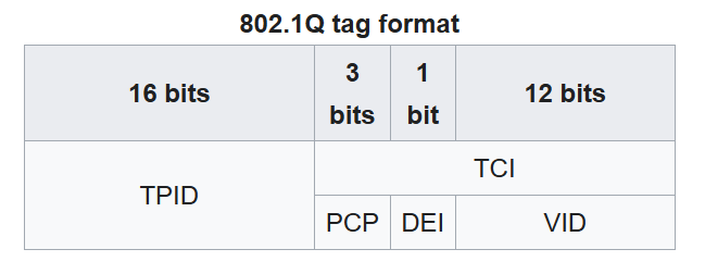
https://en.wikipedia.org/wiki/IEEE_802.1Q
802.1Q Tag - TPID (Tag Protocol Identifier)
- 16 bits (2 bytes) in length.
- Always set to a value of 0x8100 (8100). This indicates that the frame is 802.1Q-tagged.
Note
0x = hexadecimal.
802.1Q - PCP (Priority Code Point)
- 3 bits in length.
- Used for Class of Service (CoS), which prioritizes important traffic in congested networks.
802.1Q Tag - DEI (Drop Eligible Indicator)
- 1 bit in length.
- Used to indicate frames that can be dropped if the network is congested.
802.1Q Tag - VID (VLAN ID)
- 12 bits in length.
- Identifies the VLAN the frame belongs to.
- 12 bits in length = 4096 total VLANs (212), range of 0 - 4095.
- VLANs 0 and 4095 are reserved and can't be used.
- The actual range of VLANs is 1 - 4094.
VLAN Ranges
- The range of VLANs is divided into two section:
- Normal VLANs: 1 - 1005
- Extended VLANs: 1006 - 4094
Native VLAN
A native VLAN is the VLAN that carries untagged traffic on a trunk port.
- 802.1Q has a feature called native VLAN.
- The native VLAN is VLAN 1 by default on all trunk ports, however this can be manually configured on each trunk port.
- The switch does not add an 802.1Q tag to frames in the native VLAN.
- When a switch receives an untagged frame on a trunk port, it assumes the frame belongs to the native VLAN.
Note
It's very important that the native VLAN matches.
Trunk Configuration
SW1(config)#interface g0/0
SW1(config-if)#switchport mode trunk
Command rejected: An interface whose trunk encapsulation is "Auto" can not be configured to "trunk" mode.
SW1(config-if)#switchport trunk encapsulation ?
  dot1q      Interface uses only 802.1q trunking encapsulation when trunking
  isl        Interface uses only ISL trunking encapsulation when trunking
  negotiate  Device will negotiate trunking encapsulation with peer on
             interface

SW1(config-if)#switchport trunk encapsulation dot1q
SW1(config-if)#switchport mode trunk
SW1(config-if)#
These commands make Gi0/0 a trunk port, which carries traffic for multiple VLANs.
switchport mode trunkwas rejected at first. Some switches support more than one trunking encapsulation, and they won't let you turn on trunk mode while the encapsulation is still set toAuto.- Typing
?after a command shows the available options. Here the choices aredot1q,isl, andnegotiate. switchport trunk encapsulation dot1qpicks 802.1Q, the standard used today. ISL is an old Cisco-only protocol.- Once the encapsulation is set,
switchport mode trunkworks and the port becomes a trunk.
Note
On switches that only support 802.1Q, you can skip the encapsulation command and just use switchport mode trunk.
To set the native VLAN:
Note
switchport trunk native vlan vlan-id
SW1#show interfaces trunk

Port        Mode             Encapsulation  Status        Native vlan
Gi0/0       on               802.1q         trunking      1

Port        Vlans allowed on trunk
Gi0/0       1-4094

Port        Vlans allowed and active in management domain
Gi0/0       1,10,30

Port        Vlans in spanning tree forwarding state and not pruned
Gi0/0       1,10,30
SW1#
show interfaces trunk lists the trunk ports on the switch and how each one is set up.
- Mode
onmeans the port was manually set to trunk mode, and Statustrunkingmeans it's actually working as a trunk. - Encapsulation
802.1qis the tagging standard being used, and Native vlan1is the VLAN whose frames are sent untagged. - Vlans allowed on trunk shows
1-4094, which is the default. A trunk allows every VLAN unless you limit it. - Vlans allowed and active in management domain shows
1,10,30. These are the VLANs that are both allowed and actually exist on the switch, so these are the only ones the trunk really carries.
SW1(config-if)#switchport trunk allowed vlan 10,30
SW1(config-if)#do show interfaces trunk

Port        Mode             Encapsulation  Status        Native vlan
Gi0/0       on               802.1q         trunking      1

Port        Vlans allowed on trunk
Gi0/0       10,30

Port        Vlans allowed and active in management domain
Gi0/0       10,30

Port        Vlans in spanning tree forwarding state and not pruned
Gi0/0       10,30
SW1(config-if)#
switchport trunk allowed vlan 10,30 limits the trunk so it only carries VLAN 10 and VLAN 30.
- The allowed list went from
1-4094(all VLANs) down to just10,30. - VLAN 1 is no longer allowed, so its traffic won't cross this trunk anymore.
- Limiting the allowed VLANs is good practice. It keeps unnecessary traffic off the link.
SW1(config-if)#switchport trunk allowed vlan ?
  WORD    VLAN IDs of the allowed VLANs when this port is in trunking mode
  add     add VLANs to the current list
  all     all VLANs
  except  all VLANs except the following
  none    no VLANs
  remove  remove VLANs from the current list
These are the options for switchport trunk allowed vlan.
- WORD = you type the VLAN IDs yourself, like
10,30or10-20. This replaces the whole list. - add = adds VLANs to the list that's already there.
- all = allows every VLAN (this is the default).
- except = allows every VLAN apart from the ones you list.
- none = allows no VLANs at all.
- remove = takes VLANs off the current list.
Note
For security purposes, it is best to change the native VLAN to an unused VLAN.
Note
The show vlan brief command shows the access ports assigned to each VLAN, not the trunk ports that allow each VLAN. Use the show interfaces trunk command instead to confirm trunk ports.
Router on a Stick (ROAS)
R1(config)#interface g0/0
R1(config-if)#no shutdown
R1(config-if)#
*Apr 15 04:29:49.681: %LINK-3-UPDOWN: Interface GigabitEthernet0/0, changed state to up
*Apr 15 04:29:50.682: %LINEPROTO-5-UPDOWN: Line protocol on Interface GigabitEthernet0/0, changed state to up
R1(config-if)#interface g0/0.10
R1(config-subif)#encapsulation dot1q 10
R1(config-subif)#ip address 192.168.1.62 255.255.255.192
This is the router side of router-on-a-stick, where one physical router port handles the traffic of multiple VLANs.
no shutdownturns on the physical interface. Router interfaces are shut down by default.interface g0/0.10creates a subinterface. It's a virtual interface that lives on the physical port, and you make one per VLAN.encapsulation dot1q 10tells the subinterface to handle traffic tagged for VLAN 10.ip addressgives the subinterface an IP, which becomes the default gateway for the hosts in that VLAN.
Note
The number after the dot (g0/0.10) is just a label, but matching it to the VLAN ID keeps things easy to read. The VLAN is actually set by the encapsulation command.
Note
Use the show ip interface brief command to confirm the configured IP addresses.
Key points:
- ROAS is used to route between multiple VLANs using a single interface on the router and switch.
- The router interface is configured using subinterfaces. You configure the VLAN tag and IP address on each subinterface.
- The router will tag frames sent out of each subinterface with the VLAN tag configured on the subinterface.
SW1 and SW2 are connected by an 802.1Q trunk, and both ends still use the default native VLAN of 1. SW1 needs to send a frame from VLAN 1 across that trunk. How does it send the frame?
Day 18 (Part 3 - VLANs)
Native VLAN on a router (ROAS)
There are 2 methods of configuring the native VLAN on a router:
- Use the command
encapsulation dot1q vlan-id nativeon the router subinterface. - Configure the IP address for the native VLAN on the router's physical interfaces.
First method example:
R1(config)#int g0/0.10
R1(config-subif)#encapsulation dot1q 10 native
R1(config-subif)#
Second method example:
R1(config)#no interface g0/0.10
R1(config)#interface g0/0
R1(config-if)#ip address 192.168.1.62 255.255.255.192
R1(config-if)#
Note
no interface g0/0.10 deletes the subinterface.
Layer 3 (Multilayer) Switches
- Multilayer switches are capable of both switching and routing.
- Operates both at layer 2 (Data Link layer) and layer 3 (Network layer).
- You can assign IP addresses to its interfaces, like a router.
- You can create virtual interfaces for each VLAN, and assign IP addresses to those interfaces.
- You can configure routes on it.
- It can be used for inter-VLAN routing.
Inter-VLAN Routing via SVI
- SVIs (Switch Virtual Interfaces) are the virtual interfaces you can assign IP addresses to in a multilayer switch.
- You can configure hosts to use SVI as their gateway address.
- To send traffic to different subnets/VLANs, hosts will send traffic to the switch, and the switch will route the traffic.
R1(config)#no interface g0/0.10
R1(config)#no interface g0/0.20
R1(config)#no interface g0/0.30
R1(config)#default interface g0/0
Interface GigabitEthernet0/0 set to default configuration
R1(config)#do show ip interface brief
Interface              IP-Address      OK? Method Status                Protocol
GigabitEthernet0/0     unassigned      YES NVRAM  up                    up
GigabitEthernet0/0.10  unassigned      YES manual deleted               down
GigabitEthernet0/0.20  unassigned      YES manual deleted               down
GigabitEthernet0/0.30  unassigned      YES manual deleted               down
GigabitEthernet0/1     unassigned      YES NVRAM  administratively down down
GigabitEthernet0/2     unassigned      YES NVRAM  administratively down down
GigabitEthernet0/3     unassigned      YES NVRAM  administratively down down
R1(config)#
This removes the old router-on-a-stick setup from R1, so the multilayer switch can do the inter-VLAN routing instead.
no interface g0/0.10deletes a subinterface. You need one command per subinterface.default interface g0/0resets the physical interface back to its default settings, wiping any config on it.
SW2(config)#default interface g0/1
Interface GigabitEthernet0/1 set to default configuration
SW2(config)#ip routing
SW2(config)#interface g0/1
SW2(config-if)#no switchport
SW2(config-if)#ip address 192.168.1.193 255.255.255.252
SW2(config-if)#do show ip interface brief
Interface              IP-Address      OK? Method Status                Protocol
GigabitEthernet0/0     unassigned      YES unset  up                    up
GigabitEthernet0/2     unassigned      YES unset  up                    up
GigabitEthernet0/3     unassigned      YES unset  up                    up
GigabitEthernet0/1     192.168.1.193   YES manual up                    up
This turns a port on the multilayer switch into a routed port, so it behaves like a router interface.
ip routingturns on routing. A multilayer switch won't route between VLANs without it.no switchportchanges the port from a Layer 2 switchport into a Layer 3 routed port.- Once it's a routed port, you can give it an
ip addressjust like you would on a router. - In the output, G0/1 now has an IP address while the other ports show
unassigned, because they're still normal switchports.
SW2(config)#interface vlan10
SW2(config-if)#ip address 192.168.1.62 255.255.255.192
SW2(config-if)#no shutdown
This creates an SVI for VLAN 10, which acts as the gateway for the hosts in that VLAN.
interface vlan10creates the virtual interface for VLAN 10. You make one per VLAN you want to route.- The
ip addressyou give it is what the hosts in VLAN 10 use as their default gateway. no shutdownturns the SVI on. SVIs are shut down by default.
The conditions required for an SVI to be configured:
- The VLAN must exist on the switch.
- The switch must have at least one access port in the VLAN in an up/up state, AND/OR one trunk port that allows the VLAN that is in an up/up state.
- The VLAN must not be shutdown.
- The SVI must not be shutdown.
SW2 is a multilayer switch. You create interface vlan 10 and interface vlan 20, give each an IP address and enable them with no shutdown, but hosts in VLAN 10 still can't reach VLAN 20. What is missing?
Day 19
DTP (Dynamic Trunking Protocol)
- It's a Cisco proprietary protocol that allows Cisco switches to dynamically determine their interface status (
accessortrunk) without manual configuration. - It's enabled by default on all Cisco switch interfaces.
- For security purposes, manual configuration is recommended.
- DTP should be disabled on all switchports.
SW2(config-if)#switchport mode dynamic ?
  auto       Set trunking mode dynamic negotiation parameter to AUTO
  desirable  Set trunking mode dynamic negotiation parameter to DESIRABLE
-
A switchport in dynamic desirable mode will actively try to form a trunk with other Cisco switches. It will form a trunk if connected to another switchport in the following modes:
switchport mode trunkswitchport mode dynamic desirableswitchport mode dynamic auto
-
A switchport in dynamic auto mode will not actively try to form a trunk with other Cisco switches, however it will form a trunk if the switch connected to it is actively trying to form a trunk. It will form a trunk with a switchport in the following modes:
switchport mode trunkswitchport mode dynamic desirable
| Administrative Mode | Trunk | Dynamic Desirable | Access | Dynamic Auto |
|---|---|---|---|---|
| Trunk | Trunk | Trunk | X | Trunk |
| Dynamic Desirable | Trunk | Trunk | Access | Trunk |
| Access | X | Access | Access | Access |
| Dynamic Auto | Trunk | Trunk | Access | Access |
Note
DTP will not form a trunk with a router, PC, etc. The switchport will be in access mode.
More key points:
- On older switches,
switchport mode dynamic desirableis the default administrative mode. - On newer switches,
switchport mode dynamic autois the default administrative mode. - You can disable DTP negotiation on an active interface with this command:
switchport nonegotiate. - Configuring an access port with switchport mode access also disables DTP negotiation on an interface.
- It is recommended that you disable DTP on all switchports and manually configure them as access or trunk ports.
- Switches that support both 802.1Q and ISL trunk encapsulations can use DTP to negotiate the encapsulation they will use.
- ISL is favored over 802.1Q, so if both switches support ISL it will be selected.
- DTP frames are sent in VLAN1 when using ISL, or in the native VLAN when using 802.1Q.
SW1 output:
SW1(config-if)#switchport mode dynamic desirable
SW1(config-if)#do show interfaces g0/0 switchport
Name: Gi0/0
Switchport: Enabled
Administrative Mode: dynamic desirable
Operational Mode: trunk
Administrative Trunking Encapsulation: negotiate
Operational Trunking Encapsulation: isl
Negotiation of Trunking: On
VTP (VLAN Trunking Protocol)
- VTP allows you to configure VLANs on a central VTP server switch, and other switches (VTP clients) will synchronize their VLAN database to the server.
- It is designed for large networks with many VLANs, so that you don't have to configure each VLAN on every switch.
- Not recommended that you use it.
- It is rarely used.
- There are three VTP versions: 1, 2, and 3.
- There are three VTP modes: server, client, and transparent.
- Cisco switches operate in VTP server mode by default.
VTP Servers:
- They can add/modify/delete VLANs.
- Store the VLAN database in non-volatile RAM (NVRAM).
- Will increase the revision number every time a VLAN is added/modified/deleted.
Note
The revision number is used to determine the newest version of the VLAN database that the switches will synchronize to.
- They will advertise the latest version of the VLAN database on trunk interfaces.
- VTP servers also function as VTP clients.
- Therefore, a VTP server will synchronize to another VTP server with a higher revision number.
VTP Clients:
- They cannot add/modify/delete VLANs.
- They don't store the VLAN database in NVRAM. (in VTPv3, they do)
- Will synchronize their VLAN database to the server with the highest revision number in their VTP domain.
- Will advertise their VLAN database, and forward VTP advertisements to other clients over their trunk ports.
Note
Use the show vtp status command to show the status of VTP.
Note
The vtp mode client sets the VTP mode for the switch to client.
SW1#show vtp status
VTP Version capable             : 1 to 3
VTP version running             : 1
VTP Domain Name                 :
VTP Pruning Mode                : Disabled
VTP Traps Generation            : Disabled
Device ID                       : 0c09.f956.1300
Configuration last modified by 0.0.0.0 at 0-0-00 00:00:00
Local updater ID is 0.0.0.0 (no valid interface found)

Feature VLAN:
--------------
VTP Operating Mode              : Server
Maximum VLANs supported locally : 1005
Number of existing VLANs        : 5
Configuration Revision          : 0
MD5 digest                      : 0x57 0xCD 0x40 0x65 0x63 0x59 0x47 0xBD
                                  0x56 0x9D 0x4A 0x3E 0xA5 0x69 0x35 0xBC
Note
VTPv1/v2 do not support the extended VLAN range (1006-4094). Only VTPv3 supports them.
SW1(config)#vtp domain cisco
Changing VTP domain name from NULL to cisco
SW1(config)#
*May  4 02:14:47.276: %SW_VLAN-6-VTP_DOMAIN_NAME_CHG: VTP domain name changed to cisco.
SW1(config)#vlan 10
SW1(config-vlan)#name engineering
SW1(config-vlan)#exit
The vtp domain command set the VTP domain name for the switch.
Note
If a switch with no VTP domain (domain NULL) receives a VTP advertisement with a VTP domain name, it will automatically join that VTP domain.
Note
If a switch receives a VTP advertisement in the same VTP domain with a higher revision number, it will update it's VLAN database to match.
Warning
If you connect an old switch with a higher revision number to your network (and the VTP domain name matches), all switches in the domain will sync their VLAN database to that switch.
VTP Transparent mode:
- Does not participate in the VTP domain.
- Maintains its own VLAN database in NVRAM. It can add/modify/delete VLANs, but they won't be advertised to other switches.
- Will forward VTP advertisements that are in the same domain as it.
Note
The vtp mode transparent sets the VTP mode for the switch to transparent.
Note
Changing the VTP domain to an unused domain will reset the revision domain to 0.
Note
Changing the VTP mode to transparent will also reset the revision number to 0.
SW1's Gi0/0 is left in dynamic auto mode, and it connects to SW2's Gi0/0, which is also in dynamic auto. What operational mode does the link end up in?
Day 20 (Part 1 - Spanning Tree Protocol)
Network Redundancy
- Redundancy is an essential part of network design.
- Modern networks are expected to run 24/7. Even a short downtime can be disastrous for a business.
- If one network component fails, you ensure that other components will take over with little or no downtime.
- You must implement redundancy at every possible point in the network.
Note
Most PCs only have a single network interface card (NIC), so they can only be plugged into a single switch. However, important servers typically have multiple NICs, so they can be plugged into multiple switches for redundancy.
Note
The Spanning Tree Protocol (STP) is a layer 2 protocol (Data-Link Layer).
Broadcast Storms
The Ethernet header doesn't have a TTL field. These broadcast frames will loop around the network indefinitely. If enough of these looped broadcasts accumulate in the network, the network will be too congested for legitimate traffic to use the network. This is called a broadcast storm.
Note
Network congestion isn't the only problem. Each time a frame arrives on a switchport, the switch uses the source MAC address field to 'learn' the MAC address and update its MAC address table. when frames with the same MAC address repeatedly arrive on different interfaces, the switch is continuously updating the interface in its MAC address table. This is known as Mac Address Flapping.
Spanning Tree Protocol
- 'Classic Spanning Tree Protocol' is IEEE 802.1D.
- Switches from all vendors run STP by default.
- STP prevents Layer 2 loops by placing the redundant ports in a blocking state, essentially disabling the interface.
- These interfaces act as backups that can enter a forwarding state if an active (currently forwarding) interface fails.
- Interfaces in a forwarding state behave normally. They send and receive all normal traffic.
- Interfaces in a blocking state only send or receive STP messages (called BPDUs = Bridge Protocol Data Units).
Note
Spanning Tree Protocol still uses the term 'bridge'. However, when we use the term 'bridge', we really mean 'switch'. Bridges are not used in modern networks.
- By selecting which ports are forwarding and which ports are blocking, STP creates a single path to/from each point in the network. This prevents Layer 2 loops.
- There is a set of processes that STP uses to determine which ports should be forwarding and which should be blocking.
- STP-enabled switches send/receive Hello BPDUs out of all interfaces, the default timer is 2 seconds (the switch will send a Hello BPDU out of every interface, once every 2 seconds).
- If a switch receives a Hello BPDU on an interface, it knows that interface is connected to another switch (routers, PCs, etc. Do not use STP, so they do not send BPDUs).
- Switches use one field in the STP BPDU, the Bride ID field, to elect a root bridge for the network.
- The switch with the lowest Bridge ID becomes the root bridge.
- All ports on the root bridge are put in a forwarding state, and other switches in the topology must have a path to reach the root bridge.

The BPDU Bride ID fields.
The default bridge priority is 32768 on all switches, so by default the MAC address is used as a tie-breaker (lowest MAC address becomes the root bridge).
Note
The Bridge Priority is compared first. If they tie, the MAC address is then compared.
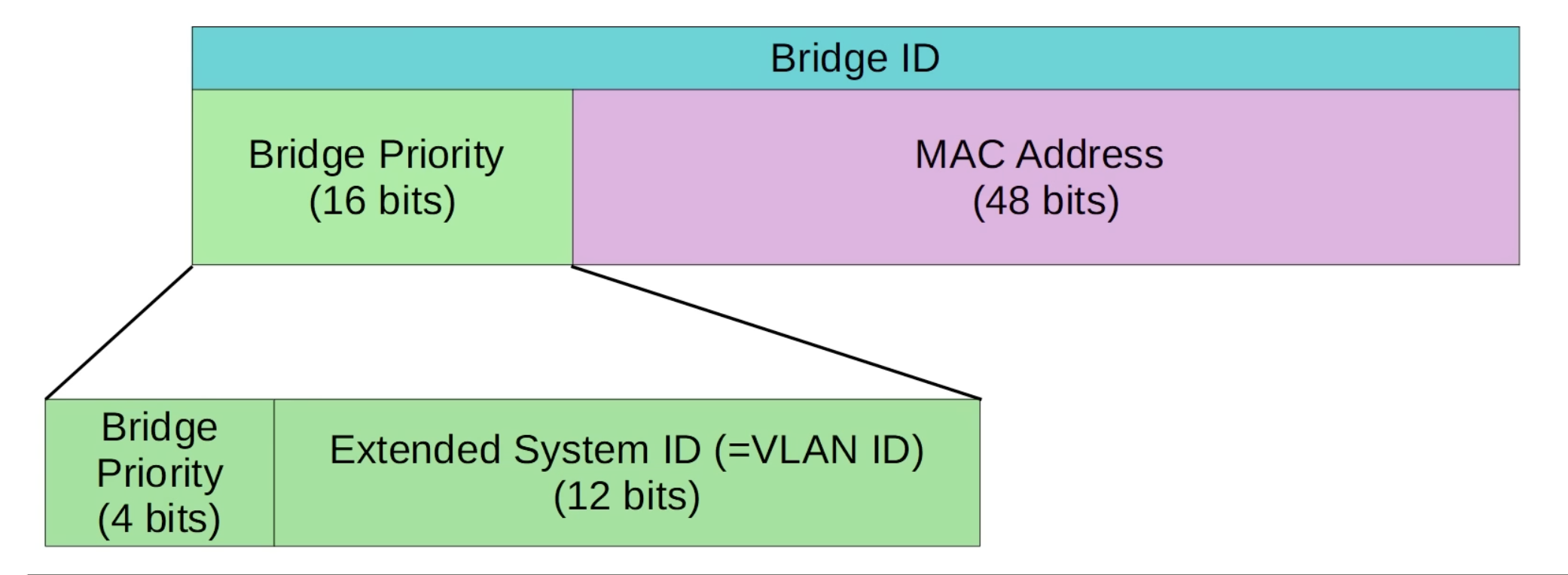
The update version of the BPDU Bride ID fields, the Bridge Priority field is now made up of two fields, Bridge Priority (4 bits) & Extended System ID (VLAN ID) (12 bits).
Note
Cisco switches use a version of STP called PVST (Per-VLAN Spanning Tree). PVST runs a separate STP 'instance' in each VLAN, so in each VLAN different interfaces can be forwarding/blocking.

Note
In the VLAN of 1, the default bridge priority is actually 32769 (32768 + 1).
Note
The bridge priority + extended system ID is a single field of the bridge ID, however the extended system ID is set and cannot be changed (because it is determined by the VLAN ID). Therefore you can only change the total bridge priority (bridge priority + extended system ID) in units of 4096, the value of least significant bit og the bridge.
Note
All interfaces on the root bridge are designated ports. Designated ports are in a forwarding state.
- When a switch is powered on, it assumes it is the root bridge.
- It will only give up its position if it receives a 'superior' BPDU (lower bridge ID).
- Once the topology has converged and all switches agree on the root bridge, only the root bridge sends BPDUs.
- Other switches in the network will forward these BPDUs, but will not generate their own original BPDUs.
The Spanning Tree Protocol process:
- The switch with the lowest bridge ID is elected as the root bridge. All ports on the root bridge are designated ports (forwarding state).
- Each remaining switch will select one of its interfaces to be its root port. The interface with the lowest root cost will be the root port.
Updated:
-
One switch is elected as the root bridge. All ports on the root bridge are designated ports (forwarding state). Root bridge selection:
- Lowest bridge ID
-
Each remaining switch will select one of its interfaces to be its root port (forwarding state). Ports across from the root port are always designated ports. Root port selection:
- Lowest root cost
- Lowest neighbor bridge ID
- Lowest neighbor port ID
-
Each remaining collision domain will select one interface to be a designated port (forwarding state). The other port in the collision domain will be non-designated (blocking). Designated port selection:
- Interface on switch with the lowest root cost.
- Interface on switch with the lowest bridge ID.
Note
STP Port ID = port priority (defaults 128) + port number.
Note
The NEIGHBOR switch's port ID is used to break the tie, not the local switch's port ID.
| Speed | STP Cost |
|---|---|
| 10 Mbps | 100 |
| 100 Mbps | 19 |
| 1 Gbps | 4 |
| 10 Gbps | 2 |
Note
Each interface has an associated Spanning Tree cost.
Three switches in VLAN 1 are electing a root bridge. SW1 has a bridge priority of 32769 and MAC address 0000.0000.0001, SW2 has 24577 and 0000.0000.00FF, and SW3 has 36865 and 0000.0000.000A. Which switch becomes the root bridge?
Day 21 (Part 2 - Spanning Tree Protocol)
Spanning Tree Port States
| STP Port State | Stable/Transitional |
|---|---|
| Blocking | Stable |
| Listening | Transitional |
| Learning | Transitional |
| Forwarding | Stable |
- Root/Designated ports remain stable in a Forwarding state.
- Non-designated ports remain stable in a Blocking state.
- Listening and Learning are transitional state which are passed through when an interface is activated, or when a Blocking port must transition to a Forwarding state due to a change in the network topology.
| STP Port State | Stable/Transitional |
|---|---|
| Blocking | Stable |
- Non-designated ports are in a Blocking state.
- Interfaces in a Blocking state are effectively disabled to prevent loops.
- Interfaces in a Blocking state do not sent/receive regular network traffic.
- Interfaces in a Blocking state receive STP BPDUs.
- Interfaces in a Blocking state do not forward STP BPDUs.
- Interfaces in a Blocking state do not learn MAC addresses.
| STP Port State | Stable/Transitional |
|---|---|
| Listening | Transitional |
- After the Blocking state, interfaces with the Designated or Root role enter the Listening state.
- Only Designated or Root ports enter the Listening state (Non-designated ports are always Blocking).
- The listening state is 15 seconds long by default. This is determined by the Forward delay timer.
- An interface in the Listening state only forwards/receives STP BPDUs.
- An interface in the Listening state does not send/receive regular traffic.
- An interface in the Listening state does not learn MAC addresses from regular traffic that arrives on the interface.
| STP Port State | Stable/Transitional |
|---|---|
| Learning | Transitional |
- After the Listening state, a Designated or Root port will enter the Learning state.
- The Learning state is 15 seconds long by default. This is determined by the Forward delay timer (the same timer is used for both the Listening and Learning states).
- An interface is the Listening state only sends/receives STP BPDUs.
- An interface in the Learning state does not send regular traffic.
- An interface in the Learning state learns MAC addresses from regular traffic that arrives on the interface.
| STP Port State | Stable/Transitional |
|---|---|
| Forwarding | Stable |
- Root and Designated ports are in a Forwarding state.
- A port in the Forwarding state operates as normal.
- A port in the Forwarding state sends/receives BPDUs.
- A port in the Forwarding state sends/receives normal traffic.
- A port in the Forwarding state learns MAC addresses.
| STP Port State | Send/Receive BPDUs | Frame forwarding (regular traffic) | MAC address learning | Stable/Transitional |
|---|---|---|---|---|
| Blocking | NO/YES | NO | NO | Stable |
| Listening | YES/YES | NO | NO | Transitional |
| Learning | YES/YES | NO | YES | Transitional |
| Forwarding | YES/YES | YES | YES | Stable |
| Disabled | NO/NO | NO | NO | Stable |
Spanning Tree Timers
| STP Timer | Purpose | Duration |
|---|---|---|
| Hello | How often the root bridge sends hello BPDUs | 2sec |
| Forward delay | How long the switch will stay in the Listening and Learning states (each state is 15 seconds = total 30 seconds) | 15sec |
| Max Age | How long an interface will wait after ceasing to receive Hello BPDUs to change the STP topology. | 20sec (10* hello) |
Note
Switches do not forward the BPDUs out of their root ports and non-designated ports, only their designated ports.
| STP Timer | Purpose | Duration |
|---|---|---|
| Max Age | How long an interface will wait to change the STP topology after ceasing to receive Hello BPDUs. The timer is reset every time a BPDU is received. | 20sec (10* hello) |
- If another BPDU is received before the max age timer counts to 0, the time will reset to 20 seconds and no changes will occur.
- If another BPDU is not received, the max age timer counts down to 0 and the switch will reevaluate its STP choices, including root bridge, and local root, designated, and non-designated ports.
- If a non-designated port is selected to become a designated or root port, it will transition from the blocking state to the listening state (15 seconds), learning state (15 seconds), and finally the forwarding state. So, it can take a total of 50 seconds for a blocking interface to transition to forwarding.
- These timers and transitional states are to make sure the loop aren't accidentally created by an interface moving to forwarding state too soon.
Note
A forwarding interface can move directly to a blocking state (there is no worry about creating a loop by blocking an interface).
Note
A blocking interface cannot move directly to forwarding state. It must go through the listening and learning states.
Spanning Tree BPDU
Remember for exam:
Dst: PVST+ (01:00:0c:cc:cc:cd)
Regular STP destination MAC address: 0180.c200.0000
Note
The STP timers on the root bridge determine the STP timers for the entire network.
Spanning Tree Optional Features (STP Toolkit) - Portfast
Warning
Portfast allows a port to move immediately to the Forwarding state, bypassing Listening and Learning. If used, it must be enabled on ports connected to end hosts. If enabled on a port connected to another switch it could cause a Layer 2 loop.
SW1(config)#interface g0/2
SW1(config-if)#spanning-tree portfast
%Warning: portfast should only be enabled on ports connected to a single
 host. Connecting hubs, concentrators, switches, bridges, etc... to this
 interface  when portfast is enabled, can cause temporary bridging loops.
 Use with CAUTION

%Portfast has been configured on GigabitEthernet0/2 but will only
 have effect when the interface is in a non-trunking mode.
SW1(config-if)#
This enables Portfast on SW1's G0/2 interface, so the port starts forwarding straight away instead of waiting 30 seconds.
interface g0/2enters the configuration for the G0/2 interface, the port you want Portfast on.spanning-tree portfastenables Portfast on that interface.
You can also enable portfast with the following command:
SW1(config)# spanning-tree portfast default
Note
This enables portfast on all access ports (not trunk ports).
Spanning Tree Optional Features (STP Toolkit) - BPDU Guard
Note
If an interface with BPDU Guard enabled receives a BPDU from another switch, the interface will be shut down to prevent a loop from forming.
SW1(config)#interface g0/2
SW1(config-if)#spanning-tree bpduguard enable
SW1(config-if)#
This enables BPDU Guard on SW1's G0/2 interface, so the port shuts itself down if a BPDU ever arrives on it.
interface g0/2enters the configuration for the G0/2 interface, the port you want BPDU Guard on.spanning-tree bpduguard enableenables BPDU Guard on that interface.
You can also enable BPDU Guard with the following command:
SW1(config)# spanning-tree portfast bpduguard default
Note
This enables BPDU guard on all Portfast-enabled interfaces.
Configure the Spanning Tree Mode
SW1(config)#spanning-tree mode ?
  mst         Multiple spanning tree mode
  pvst        Per-Vlan spanning tree mode
  rapid-pvst  Per-Vlan rapid spanning tree mode
This lists the Spanning Tree modes the switch can run. You pick one by typing it at the end of the command, for example spanning-tree mode rapid-pvst.
spanning-tree mode ?shows the available modes. The?asks the switch to list the options you can type next.mstis Multiple Spanning Tree. It groups several VLANs into a single STP instance.pvstis Per-VLAN Spanning Tree, Cisco's version of classic STP. It runs a separate STP instance in each VLAN.rapid-pvstis Rapid Per-VLAN Spanning Tree. It also runs a separate instance in each VLAN, but reacts to changes in the network much faster.
Configure the Primary Root Bridge
SW3(config)#spanning-tree vlan 1 root primary
SW3(config)#do show spanning-tree

VLAN0001
  Spanning tree enabled protocol ieee
  Root ID    Priority    24577
             Address     cccc.cccc.cccc
             This bridge is the root
             Hello Time   2 sec  Max Age 20 sec  Forward Delay 15 sec

  Bridge ID  Priority    24577  (priority 24576 sys-id-ext 1)
             Address     cccc.cccc.cccc
             Hello Time   2 sec  Max Age 20 sec  Forward Delay 15 sec
             Aging Time  15  sec
This makes SW3 the root bridge for VLAN 1, then checks that it worked.
spanning-tree vlan 1 root primarymakes SW3 the root bridge for VLAN 1. It does this by lowering SW3's bridge priority to 24576, which shows as 24577 because the VLAN ID of 1 is added to it.do show spanning-treeshows the Spanning Tree details for each VLAN. The line This bridge is the root confirms SW3 is now the root bridge.
Note
The spanning-tree vlan vlan-number root primary command sets the STP priority to 24576. If another switch already has a priority lower than 24576, it sets this switch's priority to 4096 less than the other switch's priority.
Configure the Secondary Root Bridge
SW2(config)#spanning-tree vlan 1 root secondary
SW2(config)#do show spanning-tree

VLAN0001
  Spanning tree enabled protocol ieee
  Root ID    Priority    24577
             Address     cccc.cccc.cccc
             Cost        4
             Port        1 (GigabitEthernet0/0)
             Hello Time   2 sec  Max Age 20 sec  Forward Delay 15 sec

  Bridge ID  Priority    28673  (priority 28672 sys-id-ext 1)
             Address     bbbb.bbbb.bbbb
             Hello Time   2 sec  Max Age 20 sec  Forward Delay 15 sec
             Aging Time  300 sec
This makes SW2 the secondary root bridge for VLAN 1, the backup that takes over if the root bridge fails, then checks that it worked.
spanning-tree vlan 1 root secondarymakes SW2 the backup root bridge for VLAN 1. It does this by setting SW2's bridge priority to 28672, which shows as 28673 because the VLAN ID of 1 is added to it.do show spanning-treeshows the Spanning Tree details for each VLAN. The Root ID is still SW3 (priority 24577), and SW2's own Bridge ID now has a priority of 28673, the next lowest, so SW2 becomes the root bridge if SW3 fails.
Configure STP Port Settings
SW2(config-if)#spanning-tree vlan 1 ?
  cost           Change an interface's per VLAN spanning tree path cost
  port-priority  Change an interface's spanning tree port priority

SW2(config-if)#spanning-tree vlan 1
This lists the Spanning Tree settings you can change on an interface for VLAN 1.
spanning-tree vlan 1 ?shows the settings you can change. The?asks the switch to list the options you can type next.costchanges the interface's Spanning Tree cost in that VLAN. A lower cost makes the interface more likely to be chosen as the root port.port-prioritychanges the interface's port priority, the first part of its STP port ID (128 by default). A lower port priority is preferred when the port ID is used to break a tie.
A non-designated port on SW2 is in the Blocking state when it stops receiving BPDUs. SW2 then picks that port as its new root port. With the default STP timers, how long after the last BPDU arrived does the port start forwarding regular traffic?
Day 21 (Part 1 - PortFast) STP Toolkit
PortFast - The Problem
When an end host connects to a switch port, the port becomes up/up but can't send/receive data yet. It is a Designated port but will take 30 seconds before it enters the Forwarding state:
- 15 seconds in Listening
- 15 seconds in Learning
The problem:
- This leads to a poor user experience.
- The user probably doesn't even know STP exists.
- The wait is unnecessary, because there is no risk of a Layer 2 loop occurring between a switch/PC.
PortFast - The Solution
- When PortFast is configured on a port, the port immediately enters the Forwarding state when connected to another device.
- It bypasses Listening/Learning and send/receive data right away.
PortFast Configuration
There are two ways you can configure PortFast:
spanning-tree portfast- This enables PortFast only on the individual interface.
spanning-tree portfast default- This enables PortFast on all access ports.
Note
Connections between switches are almost always trunk links.
Note
Connections to end hosts are almost always access links.
The command to show details about the spanning tree interface:
show spanning-tree interface interface-name detail
PortFast on trunk ports
- The standard PortFast configuration commands only enable PortFast on access ports.
- In some cases, you might want to enable PortFast on a trunk port:
- A port connected to a virtualization server with virtual machines (VMs) in different VLANs.
- A port connected to a router via router-on-a-stick (ROAS).
The command to configure PortFast on a trunk:
spanning-tree portfast trunk
PortFast edge
- In modern Cisco switches, the device will automatically add the edge keyword to the configuration.
Note
spanning-tree portfast disable doesn't use the edge keyword.
SW1's G0/1 is a trunk port connected to a router doing router-on-a-stick. You enter spanning-tree portfast on G0/1, but the port still spends 30 seconds in Listening and Learning before it forwards. What do you need to do?
Day 21 (Part 2 - BPDU Guard & BPDU Filter) STP Toolkit
BPDU Guard
- BPDU Guard protects the network from unauthorized switches being connected to ports intended for end hosts.
- It can be configured separately from PortFast, but both features are usually used together.
- They both enhance STP's functionality on ports intended for end hosts.
- A BPDU Guard-enabled port continues to send BPDUs, but if it receives a BPDU it enters the error-disabled state.
- In effect, this disables the port.
BPDU Guard configuration
There are two ways you can configure BPDU Guard:
Per Port:
SW3(config)# interface g0/1
SW3(config-if)# spanning-tree bpduguard enable
SW3(config-if)# do show spanning-tree interface g0/1 detail
 Port 2 (GigabitEthernet0/1) of VLAN0001 is designated forwarding
   Port path cost 4, Port priority 128, Port Identifier 128.2.
   Designated root has priority 24577, address 5254.001a.9d29
   Designated bridge has priority 32769, address 5254.0006.448f
   Designated port id is 128.2, designated path cost 4
   Timers: message age 0, forward delay 0, hold 0
   Number of transitions to forwarding state: 1
   The port is in the portfast edge mode
   Link type is point-to-point by default
   Bpdu guard is enabled
   BPDU: sent 93, received 0
spanning-tree bpduguard enable
Default:
SW3(config)# spanning-tree portfast bpduguard default
SW3(config)# do show spanning-tree interface g0/1 detail
 Port 2 (GigabitEthernet0/1) of VLAN0001 is designated forwarding
   Port path cost 4, Port priority 128, Port Identifier 128.2.
   Designated root has priority 24577, address 5254.001a.9d29
   Designated bridge has priority 32769, address 5254.0006.448f
   Designated port id is 128.2, designated path cost 4
   Timers: message age 0, forward delay 0, hold 0
   Number of transitions to forwarding state: 1
   The port is in the portfast edge mode
   Link type is point-to-point by default
   Bpdu guard is enabled by default
   BPDU: sent 165, received 0
spanning-tree portfast bpduguard default
Note
When enabled by default, BPDU Guard is activated on all Portfast-enabled ports.
Note
Use spanning-tree bpduguard disable in interface config-mode to disable it on specific ports.
ErrDisable
ErrDisable is a Cisco switch feature that disables a port under certain conditions, such as a BPDU Guard violation.
- To re-enable an err-disabled port, first solve the underlying issue.
- If you re-enable the port without fixing the issue, it will just be err-disabled again.
- You can re-enable an err-disabled port in two ways:
- Manual: use
shutdownandno shutdownto reset the disabled port. - Automatic: ErrDisable Recovery
- Manual: use
ErrDisable Recovery
ErrDisable Recovery is a feature that automatically re-enables err-disabled port after a certain period of time.
To show the status of ErrDisable Recovery:
SW3# show errdisable recovery
ErrDisable Reason            Timer Status
-----------------            --------------
arp-inspection               Disabled
bpduguard                    Disabled
channel-misconfig (STP)      Disabled
!output omitted

Timer interval: 300 seconds

Interfaces that will be enabled at the next timeout:
Note
ErrDisable Recovery is disabled by default. The default recovery timer is 300 seconds (5 minutes). Err-disabled interfaces will be automatically re-enabled after 5 minutes.
Note
errdisable recovery interval seconds modifies the interval.
Use errdisable recovery cause cause to enable ErrDisable Recovery for ports disabled by a particular cause.
SW3(config)# errdisable recovery cause bpduguard
SW3(config)# do show errdisable recovery
ErrDisable Reason            Timer Status
-----------------            --------------
arp-inspection               Disabled
bpduguard                    Enabled
channel-misconfig (STP)      Disabled

Timer interval: 300 seconds

Interfaces that will be enabled at the next timeout:

Interface       Errdisable reason       Time left(sec)
---------       -----------------       --------------
Gi0/1                  bpduguard          296
Note
The cause is typically listed under "ErrDisable Reason".
BPDU Filter - the problem
- A switch port connected to an end host continues sending BPDUs every 2 seconds.
- Regardless of whether PortFast and/or BPDU Guard are enabled.
- If the port doesn't connect to a switch, sending BPDUs is unnecessary and undesirable for a couple of reasons:
- Sending BPDUs uses some bandwidth and processing power on the switch (although it's minimal).
- BPDUs contain information about the LANs STP topology.
- If maximum security is a concern, you should avoid sending this info to user devices.
- BPDU Filter solves this by preventing a port from sending BPDUs.
BPDU Filter - the solution
- BPDU Filter stops a port from sending BPDUs.
- Unlike BPDU Guard, it does not disable the port if it receives a BPDU.
BPDU Filter can be enabled in two ways:
Per Port:
spanning-tree bpdufilter enable
- The port will not send BPDUs.
- The port will ignore any BPDUs it receives.
- It disables STP on the port.
Warning
Use with caution! BPDU Filter enabled can cause permanent Layer 2 loops.
Default (global configuration mode):
spanning-tree portfast bpdufilter default
- BPDU Filter will be activated on all PortFast-enabled ports.
- You can use
spanning-tree bpdufilter disableto disable it on specific ports. - The port will not send BPDUs.
- If the port receives a BPDU, PortFast and BPDU Filter are disabled, and it operates as a normal STP port.
BPDU Guard and BPDU Filter can be enabled on the same port at the same time:
- If BPDU Filter is enabled in global config mode and the port receives a BPDU:
- BPDU Filter will be disabled.
- BPDU Guard will be triggered (and err-disable the interface).
- If BPDU Filter is enabled in interface config mode and the port receives a BPDU:
- The BPDU will be ignored.
- BPDU Guard will not be triggered.
SW3's G0/1 has PortFast and BPDU Guard enabled, and BPDU Filter is enabled with spanning-tree portfast bpdufilter default in global configuration mode. Someone plugs a switch into G0/1 and the port receives a BPDU. What happens?
Day 21 (Part 3 - Root Guard) STP Toolkit
Root Guard: the problem
Within your own LAN, you can easily control the root bridge by setting it priority to 0. But there are cases where you might connect your LAN to other switches outside your direct control:
- A service provider offering Metro Ethernet service to your customers.
- Often used to connect sites within a MAN (Metropolitan Area Network)
Even if you set your root bridge's priority to 0, its role can be taken by another switch with a lower MAC address.
Root Guard can be configured to protect your STP topology by preventing your switches from accepting superior BPDUs from switches outside your control.
Superior BPDU = a BPDU that is superior in the STP algorithm (e.g. claiming a better root bridge ID).
Root Guard: the solution
- If you want to ensure that the root bridge remains in your LAN, you can configure Root Guard on the ports connected to switches outside your control.
The command to enable Root Guard on an interface:
spanning-tree guard root
- This enables Root Guard on the port.
- There is no command to enable it by default from global config mode.
- If a Root Guard-enabled port receives a BPDU, it will enter the Broken (Root Inconsistent) state, effectively disabling it.
- To re-enable a port disabled by Root Guard, you must solve the issue that disabled the port.
- The disabled port must stop receiving superior BPDUs.
- Tell the customer to increase the priority value of their switch.
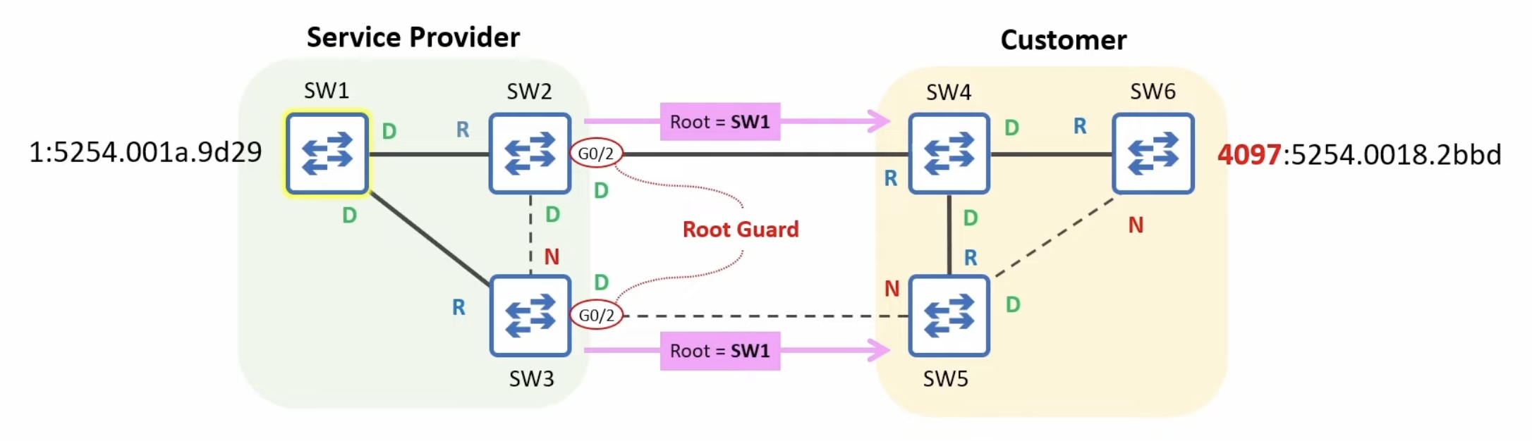
The example STP network topology.
- Once the superior BPDUs received by SW2 G0/2 and SW3 G0/3 age out, the ports will automatically be re-enabled.
- A BPDU's Max Age is 20 seconds by default.
Root Guard: CLI demonstration
SW2(config)# interface g0/2
SW2(config-if)# spanning-tree guard root
*Sep 21 08:38:56.314: %SPANTREE-2-ROOTGUARD_CONFIG_CHANGE: Root guard enabled on port GigabitEthernet0/2.
*Sep 21 08:38:56.321: %SPANTREE-2-ROOTGUARD_BLOCK: Root guard blocking port GigabitEthernet0/2 on VLAN0001.
SW2(config-if)# do show spanning-tree
!output omitted
Interface           Role Sts Cost      Prio.Nbr Type
------------------- ---- --- --------- -------- --------------------------------
Gi0/0               Root FWD 4         128.1    P2p
Gi0/1               Desg FWD 4         128.2    P2p
Gi0/2               Desg BKN*4         128.3    P2p *ROOT_Inc
BKN = Broken
ROOT_Inc = Root Inconsistent
SW2's G0/2 connects to a customer's switch and has Root Guard enabled. The customer's switch starts sending superior BPDUs, so G0/2 goes into the Broken (Root Inconsistent) state. The customer then raises the priority value of their switch. How does G0/2 start forwarding again?